Feedwater control valves play a critical role in boiler operation. One important parameter of their design is the pressure drop at the rated condition as well as off-design conditions. However, conventional methods used for establishing control valve pressure drop cannot be used at face value without reviewing all plant operating scenarios.
In power plants with drum-type boilers and constant-speed main boiler feed pumps, the feedwater control valve (also referred to as the drum level control valve) provides the means for controlling flow to the boiler. On the other hand, in power plants equipped with variable-speed turbine-driven main boiler feed pumps, the feedwater control valves are usually eliminated from the main circuit but may still be used on the startup circuit with the smaller motor-driven startup feed pump.
In either application, the feedwater control valve is in critical and severe service. As such, it must be sized and designed to provide adequate drum level control and cope with varying drum pressures expected over the range of plant operating conditions. In this regard, one of the important parameters to be evaluated is the control valve pressure drop at the rated condition, as well as during off-design conditions.
The control valve pressure drop needs to be established carefully, as it is a performance debit resulting from increase in horsepower associated with the pressure head of the boiler feed pump. Use of variable-speed drives or turbine drives on the boiler feed pump can avoid this debit by eliminating the control valve altogether. Boilers designed for sliding pressure operation generally utilize variable-speed drives or turbine drives not only to eliminate the control valve penalty but also to take advantage of minimized performance debits at part loads due to lower pump head. The part-load advantage is not available with fixed pressure operation, where boiler pressure remains constant and the pump pressure head must remain high, even at part loads.
This article highlights the various plant operating scenarios that must be considered while evaluating the control valve pressure drop. It also points to the fact that the conventional methods used in industry for establishing control valve pressure drop cannot be used in power plants without reviewing all plant operating scenarios.
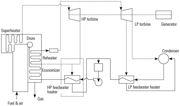
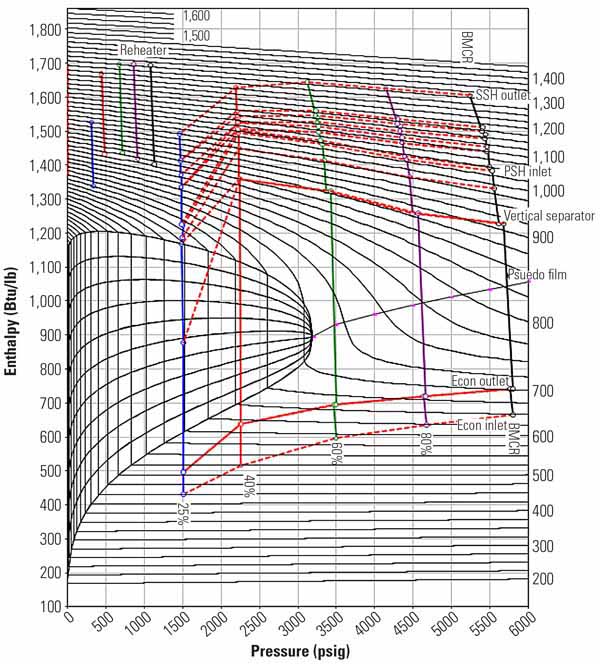
Note that the difference between the boiler feed pump head-flow curve and the system resistance curve (Figure 1) provides the basis for the pressure drop available for the drum level control valve. During startup and low-load operation, when drum pressures are low, the valve may experience severe service due to high pressure drop. These conditions could lead to valve cavitation and subsequent destruction of the valve trim along with pipe hammer, which could lead to piping and piping support damage. It is, therefore, essential that the sizing and design of the drum level control valve be such that these problems are avoided. For this purpose, the entire range of service conditions should be provided on the valve data sheet, as this will enable the valve supplier to make the correct valve/trim selection.
 |
| 1. Establishing drum level control valve pressure drop. Courtesy: Bechtel Power Corp. |
Conventional Methods for Establishing Control Valve Pressure Drop
In general industrial applications, control valve pressure drop has commonly been established by one of the three methods discussed below. However, note that these methods may not be adequate for feedwater control valve applications, which require additional evaluation taking into consideration the high static pressure head involved in pumping feedwater to the boiler.
Traditional Method. This method traces back to the ISA Handbook of Control Valves by J.W. Hutchison, which provides guidance for control valves in a pumped circuit. According to this method, the pressure drop should be 33% of the dynamic loss in the system at rated flow, or 15 psi, whichever is greater. In this context, the dynamic loss in the system is expected to include the pressure drop of the 100% open control valve. Other references allow the control valve pressure drop to be 25% to 50% of the dynamic loss in the system, exclusive of the control valve pressure drop.
Connell Method. In this method, the minimum pressure drop assigned to the control valve is based on pump discharge pressure, increased frictional pressure drop due to maximum flow rate, and base pressure drop to account for the fact that even in the wide open position the control valve generates some pressure drop. The Connell correlation is expressed in the equation below:
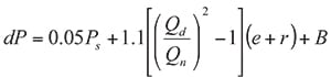
where:
dP is differential pressure,
Ps is the pressure at the beginning of the system (pump discharge),
Qd is the design flow rate in the line,
Qn is the normal flow rate in the line,
e is the differential pressure (dP) across the process equipment at normal flow,
r is the dP across only the piping and valves at normal flow, and
B is the base dP for the control valve.
Minimum Control Valve Pressure Drop Method for Pumped Application. In this method, attributed to F.C. Yu, the control valve in a pumped application is assigned a minimum pressure drop at maximum design flow rate and maximum 80% control valve open position (assuming control valve regulating range is 20% to 80% valve open position). The control valve opening is then checked at normal flow to make sure that the opening is not below the minimum 20% open limit. The minimum pressure drop is 10 to 15 psi greater than the pressure drop at valve full-open conditions.
Method Application Examples
Below is the computation used when applying the various methods for determining the assigned control valve pressure drop for the drum level control valve. Note that the values are not exactly comparative because each method uses parameters that are not common to all three methods.
Traditional Method:
- Dynamic losses = 75 psi at normal flow
- Control valve dP = 33% of dynamic losses, including control valve dP
- Therefore, dP / (75 + dP) = 0.33, where dP = 38 psi
Connell Method:
- Pump discharge pressure = 3,000 psi.
- Base dP for control valve = 11 psi.
- Dynamic losses at design flow = 1.2 times normal flow.
- Control valve dP = (0.05 x 3,000) + 1.1 x [(1.2)2 – 1] x 75 +11 = 197 psi.
Minimum Control Valve Pressure Drop Method for Pumped Application:
- Obtain valve characteristic curve showing the coefficient of flow (Cv) versus % valve opening and check Cv at 80% open (for example: Cv = 150 at 80% open).
- Using maximum design flowrate (Q) of 2,300 gallons per minute (gpm) and Cv value at 80% open, calculate the control valve dP as follows: Control valve dP = (Q / Cv) 2 x specific gravity = (2,300 / 150) 2 x 0.9 = 212 psi. Ideally, this is the pressure difference, which should be available between the pump’s head-flow curve and the system resistance curve (exclusive of the control valve pressure drop) at the maximum design flowrate of 2,300 gpm.
- Now, using the same valve characteristic curve, select the Cv at minimum controllable 20% open (for example: Cv = 45 at 20% open).
- Assume that the minimum operational flowrate (for example, 800 gpm) will be handled by the valve at minimum 20% open position, calculate the valve dP as follows: Control valve dP = (Q / Cv) 2 x specific gravity = (800 / 45) 2 x 0.9 = 284 psi. Ideally, this is the pressure difference, which should be available between the pump’s head-flow curve and the system resistance curve (exclusive of the control valve pressure drop) at the minimum operational flowrate of 800 gpm.
Note that due to high static head of a boiler feed pump in a power plant application, the Traditional Method for establishing control valve pressure drop provides a low pressure drop, which is inadequate for this application. The remaining two methods (Connell Method and Yu’s Method, or Minimum Control Valve Pressure Drop Method for Pumped Application) consider this high static head in the calculation and result in a more reasonable value. These methods can be used as the first iteration but should not be used without additional checks. The additional checks should be done to ensure that the selected valve sizing (Cv and dP) is able to deal with all operating scenarios with valve opening remaining within the acceptable controlling range of the valve. For this purpose, it is essential to recognize the various operating scenarios and functional considerations at the power plant, which impact the control valve dP.
Functional Considerations for Drum Level Control Valves
The basic functional consideration for a drum level control valve serving a power boiler is that it should be capable of covering a wide range of operating parameters.
Normal Flow Versus Minimum/Maximum Flow. In a power boiler fitted with a constant speed motor-driven pump, the drum level control valve should be capable of handling the required flow during normal plant load as well as that required at reduced load (including startup).
In addition, the drum level control valve should be capable of handling maximum flow requirements, which could arise due to a combination of feedwater flows in addition to the rated flow, such as boiler blowdown, sootblowing, or spray water usage.
If startup or low-load operation results in too severe of a range for one valve, a second startup control valve may be required to split the service conditions.
Ability to Restore Drum Level. The maximum flow requirement established should be utilized and checked against the flow requirement when trying to restore drum level from low level to normal level. In case the drum level drops to around the low-level mark and the boiler is operating under full-load conditions, it may not be possible to restore drum level without reducing load, unless the feedwater system has been designed for the extra flow capability.
Consider a boiler drum with a 3-minute storage between the normal level and the low-low level in a plant that is operating at full load. If the drum level dropped to the low-low level due to transient conditions, in order to restore drum level in a short period of time (for example, 15 minutes) without decreasing load, the feedwater pump and the associated control valve will be expected to handle 20% flow above normal load operation (since 3 minutes x 100% = 15 minutes x 20%). On the same basis, if the drum level is to be restored over a longer period (for example, 30 minutes), then the feedwater pump and the associated control valve would need to handle only 10% flow above normal load operation. This additional surge capability is built into the control valve normally operating at 80% of full travel and the pump’s design point being above the 100% operating point.
Boiler Makeup During High Drum Pressure Condition (Pressure Safety Valve Discharging). The ASME Boiler & Pressure Vessel Code, section I, paragraph PG-61.1 requires that the source of feeding shall be capable of supplying water to the boiler at a pressure of 3% higher than the highest setting of any safety valve. Under the conditions mentioned in the code, the increase in drum pressure reduces the pressure drop available to the drum level control valve. This reduces the feed flow to the drum, and the control valve is required to open further to compensate, if possible.
If the control valve is already fully open and unable to compensate for the flow reduction, then care should be taken that the reduced flow rate does not decrease to a point where it falls below the pump’s minimum flow recirculation point; otherwise, all flow will be diverted to recirculation, and no flow will reach the boiler drum. Such a condition is unacceptable, as it would violate the ASME code requirement.
A Graphic Example
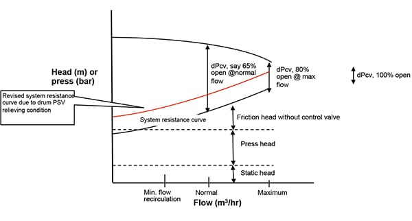
These design conditions and the control valve pressure drop variation can be well represented on a graph similar to the generic one shown in Figure 1, which includes the boiler feed pump (constant speed) head-flow curve, system resistance curve, and the control valve pressure drop (dPcv).
As flow increases, the available pressure drop across the control valve decreases. As a result, the control valve opening increases. The increase in control valve opening is, however, restricted to around 80% to 85% (due to controllability considerations), and the corresponding Cv establishes the maximum flow capability of the control valve.
Figure 1 also shows that as the pressure head increases due to high drum pressure (highest set pressure of pressure safety valve plus 3%), the system resistance line moves upward and cuts back on the available pressure drop across the control valve. At this point, the control valve opening increases, reducing the valve dP to compensate for the increase in pressure head.
The result is that the operating point moves to the left side of the head-flow curve. At this point, it is important that the control valve opening remains within its operating range; otherwise, the drum level may not be controllable. It is also critical that this operating point falls on the right hand side of the minimum recirculation flow line; otherwise, the entire flow through the feedwater pump will go toward recirculation, and no flow will reach the drum.
Specific Design Considerations
Some of the specific operating cases and functionalities of the drum level control valve that also need to be considered are discussed below.
Combined Cycle (2 x 2 x 1) Plant Operating in Single Train (1 x 1 x 1). In the case of a 2 x 2 x 1 plant—assuming one high-pressure/intermediate-pressure (HP/IP) boiler feedwater pump per heat recovery steam generator (HRSG)—the HP pressure could operate at 135 bar. However, this HP pressure could decrease significantly to 85 bar during 1 x 1 x 1 operation (50% steam turbine load). Under these conditions, the pump continues to operate along the pump characteristic curve, but due to lower pressure in the drum, the control valve closes and has to take a high-pressure drop.
The control valve pressure drop could be as high as five to six times the normal pressure drop. At this point, the question to be addressed is whether the control valve remains within the regulating range when it closes and experiences the high dP during 1 x 1 x 1 operating conditions. If at this high dP the control valve is out of regulating range, then a different base dP for the control valve must be selected.
Combined Cycle Bypass Spray Operation. On a steam turbine trip, the HRSG steam is bypassed (usually 70% to 100%) and the bypass sprays are placed in service. The HP–cold reheat (CRH) bypass valve spray water is often taken from the IP section of the HP/IP pump. However, in some cases, the IP section spray water pressure may not be high enough, and the spray water is taken from the HP discharge section of the pump. In either case, the spray water requirements enhance the flow capacity of the HP or IP section of the pump, depending on the location of the takeoff spray water line.
Consider the case of added capacity when spray water is taken from the HP discharge section and assume that the HP section flow has to be upgraded by 20% to include the bypass spray water flow. This 20% additional capacity can be considered as spare during normal operation and can be utilized, if required, for drum level makeup (from low level to normal level), for example, in a 15-minute time period.
Therefore, the drum level control valve should be suitable for handling the 20% additional flow with a significantly reduced pressure drop as projected by the difference between the pump curve and the system resistance curve. In other words, under these conditions the control valve will open wide but must remain within the regulating range of the control valve.
Combined Cycle Part-Load Operation at 75% Load. In the case of part-load operation with combustion turbine generators at 75%, the HP feedwater flow can decrease to around 60% of normal flow while the system head could decrease by around 75% to 80% (due to lower HP steam outlet pressure). With a constant speed feed pump, the lower feedwater flow along with the drop in system head requires the control valve to absorb the additional pressure drop and, as a result, the control valve tends to close. The extent of valve closure should be verified to ensure that the control valve remains within the controlling range under these conditions.
Valve Pressure Drop and Cavitation. High-pressure drop across the control valve (especially that experienced during commissioning and startup) can lead to cavitation, which can destroy the valve trim in a short period of time (within a few days of operation). Therefore, power stations have typically used a two-valve arrangement working in split range operation. The smaller sized valve (with anti-cavitation trim) is used for startup conditions, while the other, larger valve (without anti-cavitation trim or minimal anti-cavitation trim) is used for higher-load operation.
Alternatively, a single valve with a characterized disc stack can be used to handle the wide range of operation. The bottom of the trim provides low Cv values and provides anti-cavitation features, but at higher valve openings the anti-cavitation features decrease and resemble a standard trim.
Pre-operational Procedure. Note that before commissioning the boiler there are several pre-operational procedures, such as boiler fill, chemical cleaning, passivation, steam blow, and startup. For each step, the boiler drum must be supplied with feedwater, and this procedure should be clearly established up front.
Usually, the boiler is filled using the boiler fill pump because low drum pressure and low feedwater flow is outside the range of the feedwater control valve. But some of the other pre-operational steps may require the use of the startup feed pump (usually provided when using turbine-driven feedwater pumps) and its associated drum level control valve. If the drum level control valve is to be used under these circumstances, it will be subjected to high pressure drop due to low drum pressures during the pre-operational process and startup.
It is important that these cases be indicated on the valve data sheet to enable the valve vendor to provide the correct valve suitable for handling high pressure drops and any expected cavitation at low valve openings.
As an example, the commissioning startup on some subcritical boilers requires boiler passivation to be conducted by filling the boiler with feedwater and chemicals and increasing drum pressure in steps from 0 barg to 50 barg. This pressure level exceeds the capability of the boiler fill pump; therefore, the startup feed pump may be required for this operation. Such an operation imposes a high pressure drop across the drum level control valve, which should be specified accordingly.
Supercritical Boilers. Supercritical boilers do not utilize the conventional boiler drum used in subcritical boilers. Instead, they have once-through flow through the tubes, except at startup, when the boiler circulation pump is in operation along with makeup flow from the startup (motor-driven) feed pump and its associated control valve.
The startup feed pump, in some cases, is sized to serve as a standby pump as well. Such a startup/standby pump would typically be rated for 30% maximum continuous rating (MCR) flow and 100% MCR head. In such cases, the associated control valve experiences a large pressure drop during pre-start/startup conditions.
The pre-start process for supercritical boilers involves a boiler flushing operation for achieving proper water chemistry, followed by the first burner light-off (cold start). A typical flushing operation is carried out at around 20% MCR flow with no pressure in the boiler. On first burner light-off, the boiler feed is at 3% forward flow (to prevent economizer steaming) and the boiler circulating pump provides head due to 32% MCR flow around the furnace. Under these conditions, the control valve is exposed to severe operating conditions due to low flow and high pressure drop.
The pressure drop decreases during the startup sequence as the boiler pressure increases. In any case, in order to avoid valve damage, the operating conditions specified for the control valve should cover the entire range of pre-startup and startup conditions to which the valve will be subjected.
Steam Blow Operation for Boiler External Piping. During steam blow operation, the boiler drum pressure is increased to a certain value (approximately 700 to 1,100 psig, depending on the blow path) and then the blow valve is opened until the drum pressure is bled down to a low value (about 150 to 450 psig). The drum is then re-filled with feedwater at the low drum pressure, which imposes a high pressure drop across the drum level control valve. If the control valve trim is not designed for this operation, the trim could be damaged during this process.
One Size Does Not Fit All
The Connell Method and Yu’s Method may be used as a first approximation in establishing the pressure drop for the feedwater control valve. However, the value obtained from the first iteration needs to be further checked and modified as necessary. This is to ensure proper functioning of the feedwater control valve under all operating scenarios (including startup). These operating scenarios and corresponding operating parameters should be clearly identified on the valve data sheet submitted to the valve supplier.■
— S. Zaheer Akhtar, PE is a principal engineer for Bechtel Power Corp., Frederick, Md.