SYSTEM RELIABILITY
The critical subset
Some of the most interesting reliability standards are also the ones getting the most attention as we approach the transition to mandatory compliance and enforcement this summer. They are the Critical Infrastructure Protection (CIP) standards. On December 11, 2006, the Federal Energy Regulatory Commission (FERC) issued an assessment (Docket No. RM06-22-000) of the proposed CIP standards it received from the North American Electric Reliability Corp. (NERC), America’s first electric reliability organization. In the assessment, the commission said it will address approval of the CIP standards in a separate rule-making.
CIP Standards 002 through 009 are concerned with protection of the bulk electric system’s critical assets—facilities that, if damaged or disabled, would compromise the integrity of the grid or cause long, widespread outages. The cause of the damage or disabling could be physical or a cyber attack on grid control or data acquisition systems. The CIP standards are intended to give users of the bulk electric system a detailed plan for securing their portion of it through identification and deterrence of electronic attacks.
The keystone of the CIP standards is CIP-002. It requires every responsible entity (RE)—a transmission owner/operator, generator owner/operator, load-serving entity, or power marketer—to perform a risk-based assessment of its assets to determine whether any meets the definition of "critical." Any facilities that do would be subject to the requirements of CIP-003 through CIP-009. So far, NERC has outlined the broad points of such an assessment but has not detailed what it would entail. FERC’s December assessment is no help in that regard; it only states that "The methodology and process developed by a RE must be stringent and rigorous." Ideally, the absolute requirement by CIP-002 to do a risk-based assessment, and NERC’s broad outline of it, will be sufficient to generate an array of industry responses and methodologies from which a set of best practices can be culled.
Interpretive dance
One phrase that appeared in the December docket has users scratching their heads. The assessment explains that even if an RE has no operationally critical assets, any of its cyber assets that connect to control systems of others on the interconnected grid may have to be secured to block unauthorized access to the electric system. FERC calls such exposures "vectors of vulnerability," but that’s not the ambiguous term.
What is being discussed widely is language in the FERC assessment that calls on REs to use "reasonable business judgment" when interpreting the CIP standards and their requirements. To some, this is a legal term with specific precedents that may or may not serve the interests of cyber security. To others, it implies that if an RE determines that it is in its own best interest to interpret a standard one way—for example, narrowly or broadly—it could make decisions that compromise the integrity of the system as a whole.
FERC staff has reached out to various industry stakeholders and trade associations since issuing the assessment of the proposed CIP standards. One of the first questions they have asked stakeholders is their opinion of the "reasonable business judgment" phrase. Expect NERC to express its opinion when it comments on the assessment and in subsequent submittals to the commission.
No time to lose
As part of its rule-making process, FERC also will be looking closely at the schedule for implementing the CIP standards. As the standards are currently proposed, many REs must be prepared to certify that they had begun work on a CIP compliance plan by December 31, 2006.
Although FERC has neither approved the proposed standards nor issued a rule-making to implement them, the commission has stated that all REs are expected to comply with all NERC standards, regardless of their status. Many entities have already initiated the compliance efforts that the CIP standards call for. These steps include working with a regional reliability organization to develop a risk-based assessment plan, defining their own plan, and outsourcing assessments to third parties.
With the time to enforcement now down to a few months, it is time for REs to put their compliance plans in place and into effect. Implementing a compliance plan will require not only deploying the electronic tools to manage procedures, submittals, and relevant data. It also will necessitate another plan: for closely monitoring constant changes in the applicability of new standards being developed and of existing standards being modified.
—By Jim Stanton, POWER contributing editor and project manager at ICF International. He can be reached at 713-445-2000 or jstanton@icfi.com.
WORKFORCE MANAGEMENT
Aging workforce challenges
The aging of its workforce is one of the biggest challenges facing the electric utility industry. Most proposed solutions to the problem stress the importance of capturing the expertise of older workers before they retire, so that knowledge can be passed on to the next generation. An equally vexing problem is where that next generation will come from. The replacement problem is as big as the brain drain, but it isn’t addressed as often and it appears to have no obvious solution.
The traditional approach
The prevalent organization of craft workers in the energy utility sector is the apprentice-to-journeyman structure. A typical maintenance organization is delineated two ways—vertically by skill set, and horizontally by skill level in each skill set. Each skill set is a shop, with varying levels of expertise (apprentice to journeyman) in each shop. This method was used in the U.S. through most of the post-depression era up to the 1980s. It proved very successful at creating qualified workers for what were then relatively new industries.
But the approach has drawbacks, and one of the biggest is required staffing levels. The level of a craft shop’s staffing is driven by the maximum workload demand it can expect. The production pressures of planned and forced outages (especially at baseload plants) cause maintenance managers to staff for the "100-year flood." The analog in resource planning is building enough capacity to meet peak demand, which occurs only once a year.
As a result, staffing levels can far exceed the day-to-day demand on the workforce. There are both short- and long-term economic consequences of using this staffing model. The short-term effect—the underutilization of staffing resources on a daily basis—makes it very difficult to achieve excellence in O&M in the modern utility environment. The long-term effect is much more pervasive.
Legacy "assets"
Working for the local "power company" has long been considered a wise career choice because it offers job security and good benefits. The fact that many utilities are staffed by "legacy" employees has been very beneficial for utility assets. Veterans know the idiosyncrasies of equipment and systems and have developed tried-and-true methods for optimizing their operation and maintaining them in ways that extend their life. Over time, legacy employees acquire enough expertise in just the right areas that they require little continuing training, which benefits a cost-cutting utility’s bottom line.
This stability has a costly flip side, however. As more legacy employees retire, it has become financially crippling for utilities to continue paying for their excellent benefits for years or decades to come. Capital-intensive industries have been among the hardest hit by the costs of "legacy benefits." Coping mechanisms have varied by type (bankruptcies, layoffs, restructuring) and level of success. The current trend among utilities is to offer employees buy-outs and early retirement as a way of quantifying legacy costs going forward. But legacy costs represent only a subset of the tangible costs of the aging workforce. A major intangible cost is the difficulty of replacing retirees’ expertise, as mentioned at the top.
Replacing legacy workers
Several factors complicate the task of replacing workers and their experience. The first is the changing nature of utility employment. Once considered so stable that "pensioners and orphans" invested in them, electric utilities had to restructure themselves to comply with state programs that introduced retail competition in the 1980s, and the instability shattered that image. Another factor is the nature of the work: Coal-fired facilities are dirty, and restoring service following a storm entails long hours of physical exertion under daunting conditions. The travails of Entergy (post-Katrina), and Nebraska Public Power District (earlier this year, see story) are good examples.
A major obstacle to finding replacement workers is the nature of the younger workforce’s expectations. Members of the millennial generation are tech-savvy and much more comfortable with a joystick and a mouse than with a hammer and a box wrench. They also expect a collaborative work environment, which is not what the traditional apprentice-to-journeyman shop structure offers. In this model, you are expected to work your way up from the bottom.
Another challenge is competition for technically skilled workers in general. The U.S. economy is transitioning from being dominated by manufacturing to increased reliance on service jobs (which is why graduating lawyers now outnumber graduating engineers). The service economy places a premium on the skills of post-baby boomers, and its work environment more closely matches their expectations.
Gamers invited
These challenges may seem insurmountable, but they’re not. Consider how power plants have changed to take advantage of the benefits of information technology. Modern combined-cycle plants are much cleaner than the forced-draft coal plants of yesterday. Distributed control systems employ state-of-the-art technology. The calibration of a pressure instrument more closely resembles a "joystick and mouse" process than a physical process like, say, rebuilding a coal pulverizer.
Technology can also help reduce the required number of workers. Pneumatic actuators and motor operators are replacing valve hand wheels and brute force. Monitoring and diagnostic systems can replace outside operators and log-takers. The standardization of systems has reduced demands on workers’ skill levels. All of these trends will aid in addressing the staffing challenges facing the utility industry.
Renaissance men and women
Standardization and technology also call for a fresh approach to traditional staffing methodologies. One approach is making workers more multiskilled. That can be achieved to varying degrees, from simple cross-training to full-blown multicrafting. Simple cross-training develops several different skill sets that require similar types and levels of knowledge. Graduates are "operator/mechanics" or "I&C/electricians," and their combined skills improve staffing flexibility. Progress Energy’s Combustion Turbine Operations uses true multicraft technicians—trained on electrical, mechanical, and instrumentation and control systems as well as operations—at its combined- and simple-cycle facilities.
This approach has several advantages. One is reduced development costs for craft workers. The skill sets required for electricians, I&C technicians, mechanics, and operators overlap nearly 60%. It is much less expensive to raise the level of cross-trained workers’ skills than to develop individuals from scratch, as in the traditional apprentice-to-journeyman model.
Another advantage of a multiskilled workforce is that it usually makes work more collaborative. In the apprentice model, the technician with a specialty will naturally take the lead on a job involving that discipline. But with multicrafting, all technical staffers have some familiarity with many disciplines, so they can contribute to problem-solving in any area.
Implementing the concept
There are managerial challenges associated with multiskilled workforces. Progress Energy uses a "jack of all trades, master of one" approach. Familiarity with four trades is required of every technician. Each begins training with at underlying core skill, usually at or near a journeyman level. The goal of his or her training is the ability to handle the day-to-day requirements of the other three skill sets. Defining "day-to-day" correctly is the trick. Set the level of required expertise too high, and management will expect too much and technicians may despair of absorbing the content. Set the bar too low, and you may end up with a bored, underutilized technical staff.
Deploying a multiskilled workforce poses yet another challenge. Technicians naturally seek out job assignments that require their core skill. From management’s perspective, that’s a good thing because competent technicians work smarter, faster, and better. But a worker who never leaves his or her comfort zone may be unable to do a job involving another skill, if it has atrophied.
The final managerial challenge is picking the right curriculum for a training program. Don’t worry if your first choice of courses doesn’t produce the desired results. The curriculum can be adjusted over time to reflect changes in task frequency and equipment.
Becoming lean and mean
The key advantage of the multicraft workforce is that it allows a plant to be run by fewer people. Where the traditional, apprentice approach to staffing assumes a peak workload for each skilled staffer, the multicraft approach requires peak workload staffing levels for the entire site. That’s easier to achieve in practice because the journeyman electrician and the apprentice mechanic are the same person. And by including operations in the skill set, problems of workforce utilization during busy periods are lessened because any technician is qualified to run the plant.
To recap, the multicrafted workforce concept addresses three major consequences of our aging workforce. Operating lean and mean minimizes short-term and legacy staffing costs. Requiring each technician to be multiskilled mitigates the "knowledge silo" effect that has plagued the industry since baby boomers began retiring. And multicrafting makes a potential shortage of qualified workers in the future much less of a concern.
—Contributed by Tony Wiseman, lead craft technical trainer for Combustion Turbine Operations at Progress Energy. He can be reached at 919-812-4988 or anthony.wiseman@pgnmail.com.
STEAM TURBINES
Tighter tolerances in retrofits
Getting the most out of a turbine requires reducing clearances to the minimum possible. But tolerances cannot be so tight that rubbing occurs as turbines move through thermal gradients and critical speeds. Some gencos are finding that they can significantly boost their plant’s output and efficiency by retrofitting some of its systems with lighter components with tighter tolerances.
"Turbine retrofits are fairly inexpensive, and they can raise a unit’s output and power and efficiency considerably, so electric utilities are increasingly using them to increase revenue," says Peter Tavis, quality control inspector for Edison ESI, a subsidiary of Southern California Edison.
One reason why retrofits aren’t costly is that the existing casing and other components remain in place. But the casing also creates a constraint. Whereas a manufacturer of new rotors and blades can optimize their dimensions, units designed for retrofits must fit into the existing shell. Even a small gap between components can make a huge difference in performance. For example, interstage steam losses around the seals of a shaft or a blade tip can take a big toll on a turbine’s heat rate.
How much of a heat-rate penalty can be avoided by good retrofit choices? TurboCare Inc. (www.turbocare.com) explains that during normal turbine operation, retractable packing rings can ride closer to the shaft—without rubbing—than conventional rings. Based on its use of retractable rings in more than 500 turbine retrofits, the company has found that they lower a unit’s heat rate by about 2% while boosting output by up to 3%.
Brush seals, which ride even closer to the shaft than retractable seals, are another good choice. TurboCare says that in field tests, its brush seals reduced by a factor of five the steam flow around a new labyrinth seal with a nominal 7-mil (0.007-inch) gap. When a brush seal replaced a worn labyrinth seal whose gap had grown to 20 mils, the reduction was even greater—a factor of 17.
What’s under the hood?
For a retrofit to be successful, existing components must be accurately measured to ensure that the new parts fit and work better than the ones they are replacing. TurboCare explains that when it machines aftermarket parts, it doesn’t just replicate specs of original equipment manufacturer (OEM) parts, for three reasons. One is that OEMs guard those specs as intellectual property and typically won’t release drawings or data files either to a customer or a third party hired to do repairs.
Rich Olivier, TurboCare’s manager of thermodynamic design, recalls how this policy complicated a retrofit of an impulse steam turbine at a geothermal plant. "Since [the OEM wouldn’t release] the drawings, we had to open up the machine and take measurements out in the field so that the new design would fit into the existing casing," he says. "We have some structured stages that we could have applied, but they wouldn’t necessarily fit in the envelope. So we designed some new airfoil shapes from scratch."
The second reason TurboCare doesn’t rely on OEM information is that it may not reflect reality. For example, when project manager Joel Saenz opened up a 350-MW steam turbine to install a new rotor, he found that its eighth stage was displaced (Figure 1). It turned out that the "as-built" figures provided for the stage were just design specs, not actual measurements.
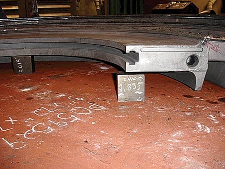
1. Out of shape. The deflection of this eighth-stage vane arc segment had to be measured before the assembly could be reengineered. Courtesy: TurboCare
"I looked at the readings from 1985 when the turbine was built, and every one was perfect. None was off by even a ten-thousandth of an inch," Saenz says. "No one has ever built a perfect machine. But based on those readings, you might conclude that this OEM had."
The third reason for taking measurements—both in the field and in the shop—prior to a retrofit is that wear and tear alters equipment clearances over time. Before designing new parts to raise turbine performance, you must quantify the condition of existing parts with great precision.
Measuring in the field
Many vendors offer specialized equipment and software that can accurately measure equipment dimensions and tolerances and convert that data into computer models of components.
"Capturing dimensions is easy," says Peter Tavis of Edison ESI. "But turning dimensional data into useful information is so difficult that most inspection houses don’t offer the service. Most arm their teams of technicians with traditional hand tools—rulers, tape measures, calipers, and plumb-bobs—for capturing 2D data in the field. They then return to their offices to assemble the data into a drawing."
Tape measures may be fine for building a house. But they’re woefully inadequate for measuring a slope of a few thousandths of an inch over a 30-foot span, or the complex pattern of an airfoil.
"By using a variety of state-of-the-art digital tools, we typically can replace a team of technicians by two operators," Tavis continues. "What’s more, these tools work in 3D and display the results on-screen in real time. So we also know in real time whether we’ve captured all the data we need."
A popular tool for taking these kinds of measurements is the FARO arm from FARO Technologies Inc. (www.faro.com). The arm is articulated and has a laser or ball-bearing probe on its end that can be moved to various points around a component to take and record measurements.
The recorded data then are converted by computer-aided design software into 3D images of the component for analysis, design, or remanufacturing. A FARO arm has a reach of about 12 feet. For larger drive trains, the tool needs to be repositioned and measurements taken from more than one location. Tavis says that by using overlapping positions, he was able to measure an entire 60-foot turbine train with an accuracy of about 50 mils.
"Typically, the technology used is determined by what needs to be measured," Robert J. Waddell, president of Applied Precision Inc. (www.appliedprecision.ca), explains. "For single-point measurements of large objects that don’t need to be so precise, an articulated arm system could be a viable option." For greater precision, he recommends a white light or laser-based system.
When using either a FARO arm or a laser device in the field, care must be taken to ensure accurate results. Bob Siedzik, a senior product engineer at TurboCare’s engineering center in Fitchburg, Mass., says that the FARO Laser Tracker can measure up to 125 feet with 1-mil accuracy—but only if the conditions are right.
"The Laser Tracker is one of the most sensitive pieces of portable 3D measurement equipment available," Siedzik says. "But it must be used indoors, or under cover outside. The Laser Tracker also is limited to ‘line of sight’ measurements, which means that it cannot see between blades."
Vibration, temperature changes, and lighting can reduce the accuracy of both laser and ball-bearing probe measuring devices. It takes experience to realize when measurements are off and to diagnose the cause.
"A smart tech can learn the measuring software in a week," says Tavis. "But understanding what needs to be recorded and how it’s done aren’t enough. Even a well-thought-out plan can fail to produce sufficiently accurate data if the tool’s setup isn’t rigid enough."
Tavis recalls seeing a measurement crew arrive at one site with a brand-new Laser Tracker. To keep the tool clean, they put a piece of plywood between it and the floor. Every time someone used the instrument, they had to step on the plywood—which moved and threw off the measurement.
"That’s a good example of a poor tool setup and an inexperienced measuring team," he says. "An inspector needs to be able to recognize when his measurements are bad."
Measuring in the shop
It’s much easier to make accurate measurements in the shop, where conditions can be controlled. Inside, permanently mounted FARO arms or CMMs (coordinate measuring machines) can provide sub-mil accuracy. TurboCare uses a Mitutoyo/Metris stationary CMM equipped with both a ball probe and laser scanner to measure components such as rotating and stationary turbine blades and turbine carrier rings (Figure 2). "This is the preferred type of tool for designing and building components with maximum precision," says Siedzik. "But because CMMs only work in the shop, they can be used only on freestanding components that have been removed from the turbine."

2. Less than a thou. In the shop, a coordinate measuring machine can measure parts’ dimensions with sub-mil accuracy. Courtesy: TurboCare
There are also white light and laser devices that capture the geometry of complex curves such as turbine blades for testing or reverse engineering. If needed, the system can project a grid of measurement points onto the surface. As Waddell explains, Applied Precision uses a Steinbichler white light system from Central Scanning Ltd. (www.central-scanning.co/uk). The system can capture up to 1.3 million measurement points in a single shot. By taking three shots from different locations, it can triangulate the position of those reference points to within 4 mils.
SPG Hydro International Inc. of Sainte-Julie, Quebec (www.spgdata3d.com), offers a multiple-camera setup for rapid 3D modeling. Rolls Royce Canada is using it to inspect turbine blades.
The bottom line is that any company performing turbine retrofits needs a wide array of tools for on-site and in-house measurements to ensure that the new parts not only fit the existing shell but also outperform what they are replacing. "There is no one piece of equipment that does everything," says Waddell.
—Drew Robb is a freelance writer who writes about issues important to the power generation industry. He can be reached at 323-660-4862.
PLANT MANAGEMENT
Writing sensible start-up and shutdown procedures
There’s a fine line to walk when writing O&M procedures because you’re writing for two separate "customers." One is the operator who will have to use the procedures. Because operators live with the plant every day (and because you may have trained them), you don’t want to insult their intelligence by making instructions unnecessarily detailed.
The other customer is an insurance inspector or regulator who may read the procedures when seeking to determine why a boiler exploded or a chemical spill occurred. For this customer, procedures need to be as specific and detailed as possible.
Following are some helpful hints for writing useful start-up and shutdown procedures:
- Arrange them in checklist form, with numbered steps. Put lines or boxes for the operator to initial and for recording when each step was completed. Time stamps provide an important record if anything goes wrong.
- Use a note to explain that each numbered step must be completed before moving on to the next one. A step is different than a note. Because notes are reminders or comments that don’t necessarily have to be completed, they should not be numbered. Example of a note: "Monitor drum levels closely as steam pressure begins to rise."
- Keep completed checklists in a historical file for a reasonable time. One year is usually sufficient.
- Avoid vague statements such as "Check the drains." Check them for what? Leakage? Whether they’re open or closed? What position should they be in?
- To the extent possible, quantify parameters. Don’t say "Check that oil pressure is normal." Say, "Check that oil pressure is between 20 and 65 psig."
- Integrate notes describing indications that the operator can expect to see after completing each step. Example: "Step (1) Turn the start/stop switch to ‘start’ and release. Note: The ‘starting cycle’ green light should come on."
- Be specific about where to execute each step. Does the operator start the gas compressor locally or from the distributed control system (DCS)? Can he rely on a DCS indication that the cooling tower fans are running, or must he visit the tower to confirm that with his own eyes and ears? Usually, local indications are better than remote ones, but it’s not always feasible to check something locally.
- Minimize acronyms, and use plain-word descriptions of components and valves. Don’t say, "Open AOV-16." Say, "Open the No. 16 Air Ejector Valve (AOV-16)."
- Conservation may be a personal virtue, but don’t try to save a tree by minimizing paper. Print the checklist in large, double-spaced type so it’s easy to read.
- Don’t use too many words for any one step. An instruction should be no more than a few sentences, not the length of a magazine article.
Open mind time
At many plants, operators who suggest improvements to procedures may have to fight through red tape to get them implemented. For example, they may have to fill out a complicated, three-page discrepancy form, send it up the corporate ladder, and wait months for a response. Or they may be asked to dial a phone number and leave a recorded message, which administrative assistants then try to interpret and type into memo form for submittal to their department head.
At least one utility plant in Florida has found a better way. Operators there can go to a computer keyboard, open a custom-designed database of operating procedures, and submit their suggested change. Comments are immediately posted to the procedure writers, who review the file three times a week. This usually generates a rapid response. But if it doesn’t, the comments remain posted right on the procedure for other operators to read.
The last step in every procedure should be a physical examination of the equipment. A veteran operator can ascertain much about a steam turbine by leaving his warm, cozy control room and walking around the unit a few times, using all five senses—and a little bit of the sixth. Old-timers know that only when standing in front of an operating machine can the complexities of the real world—the stuff that computer screens and computer print-outs ignore—be appreciated.
To their detriment, some plant managers carry this idea to the extreme and prescribe rigid operator rounds, including the punching of mechanical time clocks to record their travels. With today’s powerful DCS keeping a watchful eye, all that is accomplished by such archaic practices is the completion of forms that often end up in some rusty file cabinet without ever seeing the light of day. Veteran managers realize the morale-sapping futility of dictating their operators’ every step, and allow them some flexibility and creativity during the watch.
Once people begin doing everything "by the book," operations quickly go downhill. Workers lose interest and become bored; they forget why the company does things certain ways; and they begin to feel more like cogs in a machine than integral parts of a vibrant team. Don’t let institutional procedures take the place of human judgment.
A good compromise is to require that plant rounds—a time-honored power plant tradition—be made at least twice per shift, to keep operators alert and to get their "eyes and ears" out where they can do the most good. At competitive power plants, operators even perform minor maintenance tasks—such as such as repacking valves, oiling equipment, testing feedwater and cooling water, housekeeping, and painting—during the rounds. Prepared "rounds sheets," which list specific equipment to be checked, can help maintain consistency between shifts. But like so many other formalities in the plant, they are most effective if their users—operators—are involved in developing them.
Once rounds sheets are developed, you can easily take the next step and create oil and grease sheets. Sometimes these sheets are color-coded, with each color representing a specified type of oil or grease. This minimizes the chances of an operator pumping lightweight grease into a heavyweight application in a state of semi-consciousness at 3:00 a.m.
As an aside, one of the most commonly missed components on oil and grease sheets is the valve or damper actuator. These mechanical devices often sit in one position for extended periods of time. Without routine greasing and cycling, they may fail to operate when needed.
Keeping a written logbook goes hand-in-hand with the time-honored tradition of making rounds. And, like the rounds, a professionally maintained logbook is no less important in this age of automated control rooms. Besides serving as a valuable troubleshooting history and legal document, the logbook encourages a thorough turnover of the shift from one operator to another.
If you’ve worked in a power plant for any length of time, you know that the logbook is a source of great pride among fellow operators. It’s usually a hard-bound, sequentially numbered journal into which the operator documents the events of his or her shift, beginning with the formal, but important words: "Assumed the watch." Other entries that operators should make include:
- The general condition of the plant when the shift changes.
- Changes to operations or equipment made during the shift.
- Equipment taken out of service or locked-out/tagged-out.
- Start/stop times of special events, such as system start-ups and tests.
- The arrival time of enforcement officials, insurance inspectors, and contractors.
—POWER editors