Turbine compressors historically have been coated as an afterthought. Initially, silicone aluminum paint and diffused nickel cadmium were the only coatings available for application to both rotating components and vanes/cases. But today, the addition of a sealer can enhance the protection of centrifugal compressors in gas-processing applications in ways that a coating alone cannot. To take advantage of coating process improvements, and because some installed equipment isn’t coated by the original equipment manufacturer (OEM), on-site coating is typically the only way to go.
Coating conundrums
The goal of any coating on a turbine compressor is to maintain the surfaces of all airfoils at a low surface roughness and eliminate corrosion and fouling. But choosing a coating is a complex decision, because turbines operate in environments that often combine high humidity, high salinity, severely acidic or alkaline pollution (in chemical plants), and sand erosion. On the other hand, many turbines operate in low-humidity conditions without any extreme environmental influences.
Because of these many variables, the OEM may apply protective coatings suitable for “average” or “typical” conditions. Such coatings may perform well in some environments and fail prematurely in others, but the OEM cannot economically provide for coating protection in every different application. In fact, driven centrifugal compressors (any that aren’t integral to a gas turbine) are often not coated at all and are therefore more subject to corrosion and fouling.
In addition, the time between overhauls of all gas turbine compressors has increased, which means that compressors must function efficiently for significantly longer periods of time. That makes the quality of compressor coatings even more important.
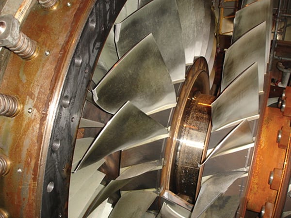
1. Gone but not forgotten. Stress corrosion at the blade base caused this blade failure. Courtesy: Sermatech International Inc.

2. Trickle-down theory. Many downstream blades are damaged by a single liberated airfoil. Courtesy: Sermatech International Inc.
Coating failure can quickly lead to blade failure due to stress corrosion, pitting, and catastrophic failure (Figure 1). Fatigue failures invariably originate with corrosion pits forming a stress riser from which a crack propagates—ultimately resulting in blade failure (Figure 2).
Though fatigue failure is a serious issue, there are other consequences of coating failure. Any increase in surface roughness results in a decrease in compressor efficiency and increased fuel consumption, which raises operating costs. In addition, aerodynamic losses in the compressor may increase exhaust gas temperatures and increase wear and hot corrosion, further increasing costs and decreasing time between overhauls.
Fouling is a drag
All compressors need a surface coating that can eliminate or mitigate fouling because the aerodynamic drag in a compressor increases with the roughness of the airfoil surfaces. Fouling consists of any deposit on a surface that contacts a moving fluid (such as air, in the case of a gas turbine), disturbs the laminar flow of that fluid, and consequently decreases the crosssectional area of the gas path. Deposits on airfoils will disturb fluid flow and increase drag even when the accumulation is not sufficient to decrease the crosssectional area of the flow path in an axial compressor.
Fouling can occur in a turbine engine through a variety of mechanisms. For example, materials dissolved in moisture, which is present in the intake air, can condense and dry on blade surfaces. Additionally, fine particles in the air can be attracted and held on surfaces by electrostatic forces.
The most prevalent source of fouling on compressor airfoils is corrosion. Corrosion results from the reaction of the metal surface with its operating environment. Corrosion is natural. All engineering metals—including iron, nickel, and aluminum—are found as compounds of oxygen and/or sulfur in nature. These compounds must be refined to produce engineering metals. Corrosion is the natural process by which these refined metals return to their natural state as compounds of either oxygen or sulfur.
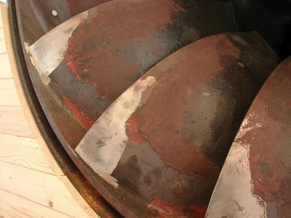
In extreme cases, corrosion consumes load-bearing metal and weakens engineering structures. Corrosion pits localize mechanical stresses and can lead to catastrophic mechanical failure. Even before pitting or loss of metal present significant mechanical problems in a turbine, rough corrosion deposits on airfoil surfaces will disturb laminar flow and diminish performance. Figure 3 presents the two types of flow with the clearly visible result of surface deposition: turbulent flow and inefficiency. Deposits lead to prolonged surface wetness; prolonged surface wetness leads to corrosion and specifically to pitting, which will preferentially occur under the deposit.

3. Rough air. Pitting and corrosion products deposited on blade surfaces disrupt the smooth airflow required for efficient operation. Source: Sermatech International Inc.
Causes of corrosion
Aqueous corrosion of metals is caused by moisture that is contaminated with ions, especially chloride and sulfate ions. The rate of corrosion is determined by:
- The length of time that the surface remains wet.
- The acidity or alkalinity of the solution on the surface.
- The exact ions present in the solution.
- The concentration of the ions in the solution (such as conductivity of the solution).
Extremes of pH—highly acidic or highly alkaline—may be more corrosive than neutral (pH = 7) solutions. For example, the low pH of rain in northern Europe, which can be 3.0 to 4.5, accelerates corrosion in industrial turbines there. Chloride and sulfate ions also tend to aggravate corrosion. For example, steel will not corrode at high pH unless chloride is present.
A gas turbine vacuums contaminants from its surroundings and concentrates them within the compressor’s intake air. These contaminants precipitate and deposit on airfoils as intake air is compressed and heated. At shutdown, these deposits absorb moisture from the air. When the deposits first begin to dissolve in water condensing on a fouled airfoil, the concentration of ions in the droplets is very high and the solution is extremely corrosive. As this cycle is repeated, gas turbines suffer aggressive corrosion and gas path surfaces roughen.
Limit fouling by treating the surface
One way of changing the response of an airfoil to its operating environment is to treat the surface with a coating. Coatings have been used for many years to manage and limit the corrosion of airfoils and entire compressors. Coatings are often the only practical alternative to control corrosion and fouling of turbine hardware.
Aluminum-filled overlay coatings are usually used in turbine applications. These coatings begin as water-based slurries of aluminum powder (<5 microns in diameter) in an acidic solution of chromates and phosphates. When these liquids are sprayed onto clean, grit-blasted metal and cured at about 650F, a tightly adherent coating is produced in which the fine aluminum particles are cemented together by an electrically insulating ceramic binder. Lightly blasting this coating with grit, glass beads, or other media removes the insulating binder from the surfaces and makes the coating electrically conductive. (The coating also becomes conductive if heated between 950F and 1,200F. At these temperatures, a conductive ionic solid, AIP, forms between the particles as the binder and aluminum react.) When the electrical resistance of the aluminum-filled composite coating is less then 15 ohms, it is galvanically sacrificial on steels. If damaged, the coating will corrode in place of the steel.
Improvements in these coatings began with a need for smoother coatings. Smoothness was increased by vibratory finishing of airfoils. Polished aluminum coatings are smooth, but they are not inert. Aluminum reacts with oxygen to form a protective scale; it also reacts with chloride ion and sulfate ion, creating corrosion products. Though they cause no corrosion or attack on the substrate material, aluminum corrosion products increase surface roughness, and fouling will occur.
A further coating improvement was a process that combined the reduced surface finish of the polished aluminum coating with a compatible inert sealer layer. This coating process was unique in that it achieved a low surface profile without the need for vibrating finishing.
The basic properties of sealed metallic ceramic coatings described in Table 1 indicate that this coating system has the necessary properties to limit fouling and corrosion in many axial compressors. However, it is not designed to deal with chemical fouling due to polymerization, salt formation, and wet gas fouling often encountered with centrifugal compressors in gas-processing applications. In these situations, a different kind of sealer is applied over the galvanically active aluminum coating. The sealer is a proprietary two-part polymeric film that provides inhibitive corrosion protection and a hard, nonstick organic barrier layer. General properties of this coating system are described in Table 2.
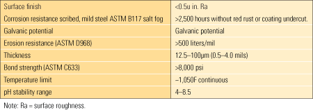
Table 1. Properties of sealed aluminum-ceramic coatings. Source: Sermatech International Inc.

Table 2. Properties of centrifugal compressor coating. Source: Sermatech International Inc.
Coating goals
The goals of applying any on-site coatings include the following:
- To return compressor components to a condition similar to that of new components using appropriate coatings. This is a goal—not a guarantee—because of the extent of pitting sometimes seen.
- To ensure that airfoils are inspected for pits and other metallurgical concerns.
- To select an appropriate coating based on the operating conditions to which that the specific compressor is exposed. Coating systems can often be specifically tailored for each application.
- To review the existing coating in terms of which airfoils were coated and which were not in an effort to improve overall compressor performance. Previously uncoated airfoils usually should be coated.
- To analyze, in the case of centrifugal compressors, the operating conditions and select a coating and process to optimize performance. Note that many centrifugal compressors have historically been operated without coatings and are subject to corrosion and severe fouling.
Process steps for axial compressors
On-site coating work requires the same infrastructural equipment that would be used at an overhaul shop or coating application facility:
- Handling equipment suitable for the components being coated
- Water supply
- Electrical power
- Clean compressed air (free of oil and water)
- Natural gas/propane
- An air-conditioned storage area for consumables
- Waste management
Depending on the size and nature of the components to be coated, various shapes and sizes of ovens will be required. Surface preparation equipment will also will vary. However, the overall process steps remain the same whether one is coating a rotor, diaphragm, bladed wheel, or a compressor case:
- 1. Steam-clean the component(s) and check for cracks.
- 2. Visually inspect, and clean as necessary. Figure 4 shows a typical rotor in the corroded condition.
- 3. Lightly dress and blend airfoils.
- 4. Grit-blast all surfaces to be coated (removing all old coatings, oxidation, and rust), masking areas not be coated (shafts, seal areas, and internal surfaces of rotors). Figure 5 contrasts blades that have been blasted with dirty blades.
- 5. Do a thermal degreasing in which components are heated to a temperature slightly above the coating cure temperature to remove residual oil, grease, and other contaminants.
- 6. Mask as required.
- 7. Apply the basecoat material. All applicable basecoats have water as the only solvent. Consequently, humidity control in the spraying booth area is essential for applying smooth, uniform coatings of the correct thickness. Figure 6 shows the application of basecoat material.
- 8. Cure the basecoat. The applied coating is allowed to dry to a uniform grey color. Then it is heated, dried at about 176F, and cured at about 653F. The total time of cure is dependent on the mass, heat-up rate, and part configuration.
- 9. Burnish the basecoat by lightly blasting it with glass beads or by burnishing with aluminum oxide abrasive.
- 10. Check burnished surfaces with a multimeter to ensure that the coating is electrically conductive. A conductive coating is sacrificial to steel and will preferentially corrode in hostile saline environments.
- 11. Apply a topcoat. Topcoats create a sealed inert coating surface to resist all kinds of fouling, including corrosion. A ceramic sealer in this case creates a surface of high electrical resistance and low surface roughness. A polymer topcoat is used instead in order to resist organic fouling.
- 12. Inspect for thickness, surface finish, and proper cure.

4. Rusty blades. This was the as-received condition of a gas turbine rotor before it began the reconditioning process. Courtesy: Sermatech International Inc.

5. No deposit, no return. Grit-blasting the blade surface prepares the rotor for the protective coating process. This is the same rotor shown in Figure 4. Courtesy: Sermatech International Inc.

6. Full coverage. A technician applies a basecoat to the rotor shown in Figure 4. Courtesy: Sermatech International Inc.
Coating equipment
Although the on-site coating process is designed to produce the same quality coating systems as would be produced in a standard production facility, the equipment is different because it must be portable and more versatile. Typically, a “Mobile Workshop” packaged as two independent containers is shipped to the project site. The units include an oven capable of 660F operation, a blasting/burnishing cabinet, and a spray booth area. This unit can be used for loose axial compressor diaphrams, bladed wheels, and centrifugal compressor diaphragms.
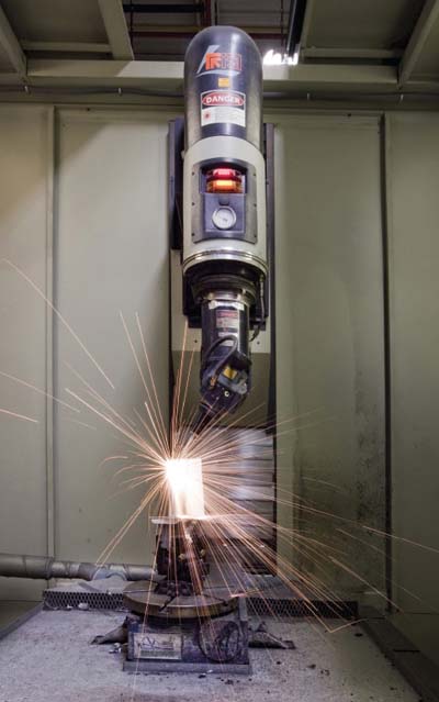
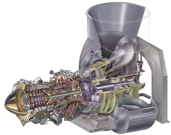
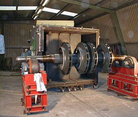
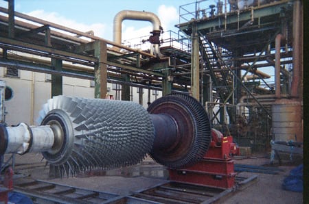
The equipment necessary to coat larger components, such as cases and rotors, is larger and more complex. It is necessary to monitor the temperature of rotors and to rotate them continuously during heat-up, curing, and cool-down cycles. A smaller oven suitable for centrifugal compressor rotors is shown in Figure 7 in a half-shell configuration. Figure 8 shows the centrifugal compressor after leaving the oven, ready to be reinstalled. Figure 9 shows an entire industrial gas turbine compressor that was cleaned and coated on-site, ready to be reinstalled.
7. Rotor rotisserie. A centrifugal compressor rotor is sealed in an oven to cure the final coating. The rotor is slowly rotated during the heat-curing process. Courtesy: Sermatech International Inc.

8. Final product. This is the centrifugal compressor rotor shown in Figure 7 after the coating has cured and cooled. Courtesy: Sermatech International Inc.
9. Compressor makeover. This industrial gas turbine compressor was cleaned and recoated on-site. Courtesy: Sermatech International Inc.
Calculating performance improvement
Each overhaul operation step can be analyzed and a performance improvement can be calculated for that step as a percent efficiency improvement, a reduction in exhaust temperature, an increase in output performance, or some other factor. Unfortunately, during an overhaul, many variables are changed: New airfoils are added, and the performance of all components is optimized, so sorting out the effect of single component changes, such as compressor coatings, becomes very difficult.
On the other hand, it is known that the smooth sealed aluminum coatings described here have been shown to improve the efficiency of flying turbines by 1.0% to 1.7% as measured by thrust-specific fuel consumption. Efficiency improvement is estimated to be 1.0% to 1.5% in output at equal fuel flow. At equal output, a heat rate decrease of 0.5% to 1.0% can be estimated.
In one specific application of the coatings described here on two Westinghouse 501F compressors at Florida Power & Light, calculations of payback time for the coating application investment were made. In this case, the compressor was not recoated in the first overhaul session and efficiency was not calculated; during the next overhaul, it was coated. All other overhaul operations were the same. It was estimated that the coating payback time was less than three months.
When considering centrifugal compressors, calculations are somewhat different in that the ability of a coating to resist fouling is measured by the number of months of operation until a certain predetermined efficiency drop is reached. Though this may be a difficult measurement in the real world because of all the variables, it has been shown that in applications involving ethylene compressors, coating a unit can double its useful lifetime between overhauls compared with an uncoated compressor. Such improvements vary from machine to machine in different applications and cannot be guaranteed.
—Mark F. Mosser (mmosser@sermatech.com) is senior scientist for Sermatech International Inc. Science and Technology Center. Paul Brooks (pbrooks@sermatech.com) is international industrial gas turbine manager at Sermatech UK Ltd.