Laser Hole-Shaping Improves Combustion Turbine Efficiency
Cylindrical holes were once the industry standard for air film cooling on turbine engine components. The cooling holes were traditionally formed using an electro-discharge machine (EDM) with a round electrode that slowly eroded the component alloy away until a complete hole was formed. The task was time-consuming and costly, because a typical combustion turbine blade required hundreds of holes.
As coatings technology progressed, turbine manufacturers added a ceramic thermal barrier coating (TBC) to protect blades as the pursuit of higher operating efficiencies pushed up gas temperatures some years ago. Unfortunately, that made EDM shaping through a TBC coating applied to blades and vanes impossible. One major limitation of the EDM process is that it requires a surface material to be conductive, because the process requires an electrical circuit path to function.
The process of applying shaped holes on turbine airfoils then evolved into a two-step machining process sandwiched around the application of a TBC. Before a ceramic nonconductive coating could be applied, cylindrical airfoil holes were drilled with a laser. Laser drilling focuses a high-energy beam of coherent monochromatic light at the surface of the airfoil to melt the alloy.
Next, the external TBC was applied to the surface of the turbine components to protect the alloy. However, the laser-drilled holes could be blocked if overcoated, thus reducing the efficiency of the intended blade cooling design. Normally, a mathematical formula was used to determine hole coatdown based on hole size and amount of coating thickness. The final application of the TBC also created yet another airflow disturbance step.
In the second machining step, a specially shaped EDM electrode was superimposed in each laser hole to produce a round metering hole with a diffuser shape at the surface. This diffuser shape (unlike the traditional round exit hole) spreads the exiting airflow and promotes more uniform surface cooling effect. Because it was a two-step process, there was a possibility for many hole-to-shape mismatches that impede the smooth transition of the airflow. The entire process was time-consuming, and rework was often required to produce a blade that met specification. At the time, this process technology helped to usher in the next generation of advanced turbine engine components.
New Laser Technology Speeds Drilling
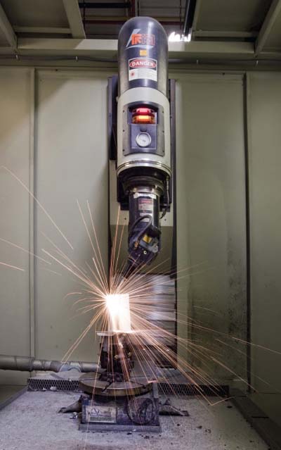
Today, most turbine components require some form of nonconductive TBC, thus, final dimension shaping through the TBC is made possible by the many new developments in laser shaping technology. And this laser shaping technology is not limited by the application of coatings prior to the hole drilling or shaping process. Laser shaping technology has evolved from a two-step process into a single process that drills and shapes holes through a TBC, bond coat, and airfoil base metal to create a finished product (Figure 1).

1. Full service. Today’s advanced laser drill and shape tools can produce a completed blade by drilling through the ceramic thermal barrier coating applied earlier. Earlier process required the ceramic coating to be applied after the laser drill and ship, causing quality problems. Courtesy: Chromalloy
This one-step process drills hole openings shaped like a trapezoid with the downstream portion of each hole opening at the airfoil surface, either flaring or widening relative to the narrower upstream portion of each hole opening. This design allows the cooling air to be distributed completely over the convex and concave surfaces of the airfoil or platform. The increasing cross-sectional area of the cooling hole opening functions as a diffuser to reduce the velocity of the cooling airstreams exiting the holes. Lower-velocity airstreams are more inclined to cling to the blade surface than to separate and reduce the effectiveness of the film cooling of the component surface.
Laser Drilling and Shaping
The latest laser shaping processes also allow for much more complex heat transfer designs to be added to the surface of a blade or other component, also in a single step. All of the cooling holes and shape segments are formed with a single drill and shape process, seamlessly producing complex diffuser shapes that previously required multiple processes. The shape, also perfectly superimposed over the hole, creates the uniform airflow over the airfoil surface, as the heat transfer engineer originally intended. Another advantage: The final dimension of the laser-drilled and -shaped component is the finished dimension, as all the coatings were applied earlier in the process. The mechanical impact of the laser drilling and shaping process on the TBC is negligible (Figure 2).

2. Laser hole shaping. The laser can produce shaped and directional holes to manage the cooling air flowing through the blade. This blade has completed its laser drilling and shaping and is ready for a final quality check before shipping. The white portion of the blade is the ceramic thermal barrier coating that protects the blade so that it can operate at higher temperatures. Courtesy: Chromalloy
Today, Chromalloy uses this single-step laser drill and shape technology to produce a significant number of turbine airfoils for industrial gas turbine operators plus other commercial and military aircraft operators.
— Contributed by Frank J. Wos ([email protected]), director of laser technology, Chromalloy.