A utility evaluated various methods of obtaining a NOx reduction of at least 30%, as required by upcoming regulations for its boiler, which originally produced 0.54 lb of NOx/million Btu at 410 MW full load. Nalco Mobotec engineers performed a computational fluid dynamics (CFD) simulation of the boiler to first understand the boiler’s combustion process and then determine the most economical method to achieve the required NOx reduction.
Nalco Mobotec’s Rotamix selective noncatalytic reduction (SNCR) system injects urea into the furnace, using a boosted air delivery system to transport urea deep into the furnace flue gas cross-flow. The key to an economical installation is to minimize the number of injection ports while obtaining a good concentration of urea in the areas where NOx is concentrated.
The Riley rear-wall-fired boiler was originally designed to burn oil, so when it was converted to fire eastern bituminous coal, there was insufficient residence time for coal combustion. The unit routinely has upper furnace post-combustion, superheater tube temperature alarms, high CO, and overall poor combustion. In the past, 28 Babcock & Wilcox low-NOx burners were installed on the rear wall with seven two-chamber overfire air (OFA) ports on the front wall. Due to poor mixing between the OFA and the flue gas, deep staging for further NOx reduction has been limited by poor post-combustion, leading to high upper furnace temperatures.
Nalco Mobotec engineers began their analysis with a simulation of the existing boiler operation to develop a better understanding of its operation. Initially, the original boiler was simulated for a better understanding of its operation—the first step in developing an optimal NOx reduction solution. The engineers selected FLUENT software, a CFD package from ANSYS Inc., because it is capable of accurately modeling thermal NOx, prompt-NOx, fuel-NOx formation, as well as SNCR NOx reduction.
Modeling the furnace
In the computer model, the furnace geometry was represented with an unstructured grid consisting of approximately 780,000 computational cells. This mesh used a mix of tetrahedral and hexahedral elements (Figure 3). The CFD model included the entire radiant furnace, beginning at the burner throat or OFA face (where inlet boundary conditions were imposed) and ending at the vertical rear wall tubes at the top of the furnace (where outlet boundary conditions were imposed). The CFD model domain extends through the backpass down to the economizer and into the ductwork in order to represent the correct flow field in the upper furnace and to stabilize the numerical solution by preventing any reverse flow or recirculation at the exit boundary.
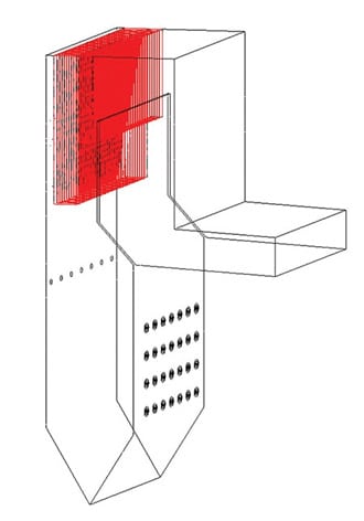
3. Start at the beginning. Nalco Mobotec engineers were charged with reducing emissions on a utility boiler using SNCR. Their first step was to develop a CFD model of the boiler in the “as found” condition. Source: Nalco Mobotec
Engineers properly entered the system information in the model, including firing rate and system load, and coal properties, such as composition and fineness. Burner swirling patterns and the firing configuration were implemented in the model through inlet boundary conditions.
Rotamix SNCR system
Nalco Mobotec engineers then simulated the furnace with the SNCR system added. This system uses lance-by-lance flow control and is continuously biased by a feedback-control algorithm to react quickly to coal changes, sootblowing, and load in order to tune the system to reduce NOx and slip simultaneously.
The SNCR system includes duct humidification of the boost air, which provides an additional control parameter for timing the chemical availability of the urea to the appropriate NOx reduction chemistry temperature window. In SNCR design, the goal is to expose all of the urea to as much of the flue gas as possible at temperatures between 1,700F and 2,000F. Above this temperature range, urea will actually react to form NOx. Below this temperature range, isocyanic acid (HNCO) and ammonia (NH3) will slip or escape from the hot furnace. Excessive slip can cause binding with sulfur dioxide to form ammonium bisulphate, which agglomerates in the ducting as pluggage or condenses into ash.
Optimizing SNCR design
The key challenge for Nalco Mobotec engineers was designing the system to deliver the required reduction in NOx while minimizing the installation cost. The primary design parameter is the number and location of the injection ports that are used to inject urea. Injection ports add cost not only because of the labor and material they require but also because of the parasitic power loss required to inject urea into the furnace. Having more ports also means more power is needed to inject urea into the furnace.
The CFD simulation results for the temperature distribution over two vertical planes are shown in Figure 4a. The maximum flame temperature in the baseline furnace is about 3,300F. The temperature distribution indicates that coal ignites soon after being injected into the furnace, which is consistent with firsthand observations of actual furnace operation through view ports.
Along the cross section of each burner, ignition first occurs on the boundary between the primary flow and the surrounding flow. The flame then propagates and expands into the center of the furnace. The biasing of the combustion to the front wall can be seen from the oxygen distribution in Figure 4b. In the region between the burner zone and the nose, the oxygen concentration is virtually zero along the front wall opposite the burners and below the OFA.
The oxygen mal-distribution in the lower furnace causes carbon monoxide to be burned slowly and to extend downstream of the nose, as shown in Figure 4c. The formation of carbon monoxide begins near the burners, and the concentration persists along the fuel stream into the furnace. As secondary air mixes with the primary fuel stream, carbon monoxide concentration drops. The average carbon monoxide concentration at the furnace exit is approximately 20 ppm. There are zones of high carbon monoxide between some of the pendants, particularly in the pendant gaps that are not directly above an OFA port.
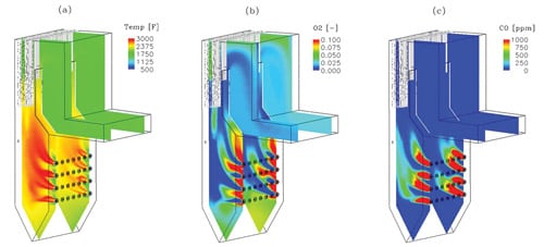
4. The simulation speaks. Sample results from the CFD simulation for (a) gas temperature, (b) oxygen, and (c) carbon monoxide distribution. Source: Nalco Mobotec
The upper furnace temperature is shown in Figure 5 with a temperature scale from 1,700F to 2,400F. Since urea chemistry for NOx reduction is best within a temperature window of 1,700F to 2,000F, this temperature scale best shows the region of the furnace that is available for SNCR NOx reduction. This temperature plot shows air injection without urea. Urea can be injected into areas in which the temperature exceeds 2,000F because of the time delay required for mixing.
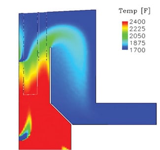
5. Waiting for burnout. A fuel switch from oil to eastern bituminous coal means there is little residence time in the furnace for carbon burnout before combustion gases enter the backpass. This figure shows predicted temperature distribution in the upper furnace. Source: Nalco Mobotec
Optimized design provides high returns
The next step was adding the SNCR injectors to the model and viewing the results. The CFD NOx calculation with chemical kinetics was performed, and the results are presented in Figure 6. Here, the NO concentration at the exit of the radiant furnace is compared with and without urea injection. This figure shows that urea injection provides a substantial reduction in NOx. Blue and teal regions and the surrounding green areas indicate where the greatest NOx reduction occurs. The total predicted NOx reduction is 32% for this case. This reduction is concentrated in a localized area, representing less than 50% of the cross section of the boiler. On a practical level, there is no injection system that can cover the rest of the area for this large unit.
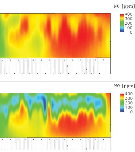
6. Visual results. NO concentration (top) without and (bottom) with urea injection. Source: Nalco Mobotec
Based on the CFD simulations, Nalco Mobotec engineers decided to inject urea at 50 injectors. Urea flow to each injection port was controlled as a function of boiler load. After the SNCR was installed, the CFD predictions for SNCR NOx reduction were compared with the full load field data, as shown in Table 2.
Table 2. Accurate predictions. CFD predictions of NOx reduction show good agreement with field measurements. Source: ANSYS/Nalco Mobotec
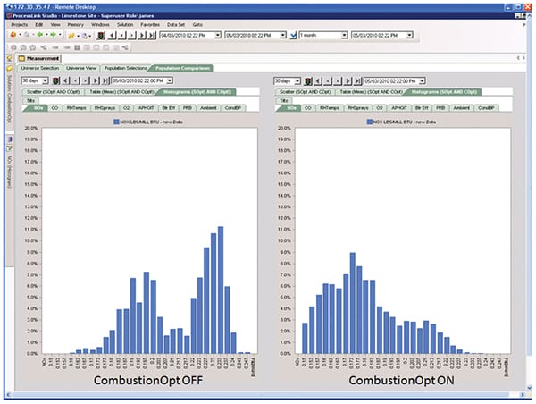
Field measurements showed that 0.54 lb/million Btu of baseline NOx was produced by the furnace prior to the SNCR installation, compared with 0.50 lb/million Btu predicted by the CFD model. Field measurements also showed that 0.35 lb/million Btu of NOx was generated after the SNCR installation, compared with the 0.34 lb/million Btu predicted by CFD. The remarkable accuracy of the CFD predictions demonstrates the power of this technology and why it is popular in the power generation industry.
Table 2 also shows that, at a full load of 3,952 million Btu/hr, the SNCR reduced NOx from 0.54 lb/million Btu to 0.35 lb/million Btu. Over the North Carolina 12-month ozone season, with a capacity factor of 80%, this results in a reduction of 3,426 tons of NOx emissions per year. With NOx credits trading at $2,000 per ton, $6.9 million per year of revenue is generated.
The recurring costs of operating the SNCR, primarily urea, are approximately $1.5 million per year. The capital cost associated with installing the SNCR was approximately $2.5 million. Both operating costs and capital costs were kept low on the project by utilizing CFD to optimize placement of the injection ports. As a result, the SNCR paid back its cost in less than six months, generating an additional $5.7 million in net revenue per year for the utility owner since that time.
—Contributed by Dr. Gui-su Liu (gliu@nalcomobotec.com), senior combustion scientist and Dr. Brian S. Higgins (bhiggins@nalcomobotec.com), VP of technology at Nalco Mobotec.