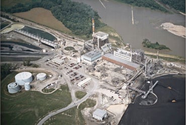
Like many older coal-fired plants, Westar Energy’s Jeffrey Energy Center (JEC) was built with traditional, pneumatic flyash-handling and removal systems. Such systems collect flyash in hoppers attached to the bottom of a unit’s electrostatic precipitator (ESP) and/or baghouse. Periodically, the hoppers are emptied into tanks and the flyash is conveyed away for disposal or beneficiation.
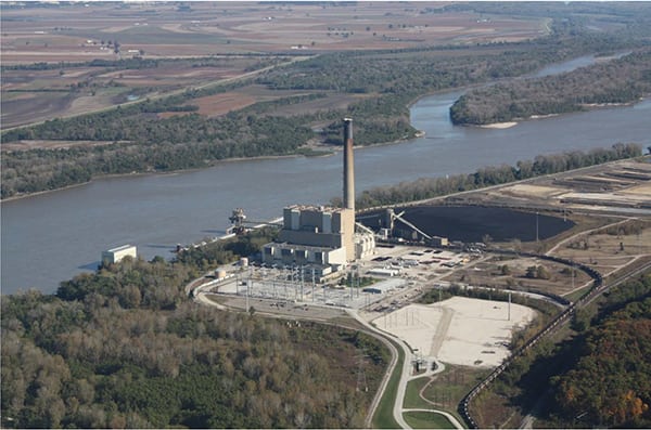
JEC, near St. Marys, Kansas, has three 800-MW units that burn Powder River Basin (PRB) coal. Unit 1 entered commercial service in 1978, Unit 2 in 1979, and Unit 3 in 1983.
The problem with pneumatic flyash systems of that vintage is their inherent need for lots of maintenance. At JEC, for example, the systems have chronically experienced two kinds of problems since their start-up more than two decades ago. One was the frequent backup of ash in the hoppers. When a hopper became clogged, its unit had to be shut down to manually remove the ash — incurring heavy revenue losses and cleanup costs. The problem was so bad that JEC had to assign two full-time maintenance workers to the hoppers to keep them working.
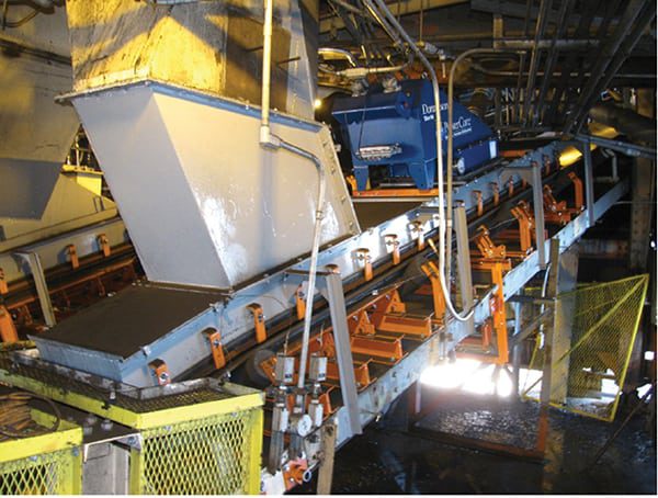
The other problem was just as serious and costly: frequent failures of system components constantly exposed to abrasive flyash. In 2003 alone, JEC experienced 177 diaphragm failures in the 52 cycling intake and gate valves of its three ash-handling systems (Figure 1).
1. Jeffrey Energy Center’s old pneumatic flyash handling system’s many cycling valves were expensive to maintain. Courtesy: Westar Energy
At this point, with maintenance costs rising and flyash-handling capacity falling, top executives of JEC and Westar finally made the decision to upgrade the plant’s flyash-handling/removal system to a different design.
Weighing the Options
Rather than commit to a particular system technology or design, the managers of the upgrade project requested bids for the following:
-
A vacuum-only system
-
A vacuum/pressure transfer system
-
A dense-phase pressure system
-
A continuous flyash removal system
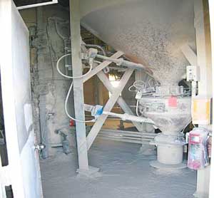
A vacuum-only system would be most like the plant’s existing pneumatic system. However, retrofitting it would require replacing more than 1,000 feet of existing piping with larger-diameter pipes at considerable cost and replacing existing water-powered exhausters with mechanical exhausters. In addition, the capacity of the ash separation equipment above the ash silos (Figure 2) would have to be increased — no easy task, given its complexity. The project managers began to have misgivings about the maintainability of a vacuum-only system. One bidder suggested a system with 53 moving parts: 50 gate valves, two mechanical exhausters, and one fluidizing air blower.
2. Ash separation equipment mounted above the storage silos required constant housekeeping. Courtesy: Westar Energy
By comparison, a vacuum/pressure transfer system would have two big advantages: No piping would need to be replaced, and increasing the system’s conveying capacity in the future would only require increasing the size of its blowers. However, although a vacuum/pressure transfer system would improve access to the ash separation equipment, JEC managers ruled out this design because it would require constant changing of filter bags, thereby increasing maintenance costs, rather than decreasing them, which was the project’s main goal.
The third option — a dense-phase pressure system — was briefly considered for its main benefit: a big increase in ash transport capacity. However, because ash would come from all three silos at the same time, managers ruled out this design, too, due to concerns that ash would plug piping.
The last system evaluated was an Airslide continuous flyash removal system offered by the Pneumatic Transport division of F.L. Smidth Inc. (www.fls-pt.com). The Airslide system has three major advantages: no high-maintenance cycling gates, no need to store ash in ESP hoppers, and no need for ash separation equipment. To further address managers’ concerns about maintenance, F.L. Smidth guaranteed that the system’s patented Airslide fabric would last for more than 10 years and that its integral Fuller-Kinyon pumps would operate two or three years with no need for maintenance of any kind. The system’s big drawback, however, was its capital cost, which was the highest of the four system types considered.
After weighing all four options, Westar Energy decided to buy the Airslide system and retrofit it on JEC Unit 1. F.L. Smidth was given an order for the equipment, and Burns & McDonnell was hired to handle system design and layout.
Start-Up and Shakedown
Shortly after the system was installed and commissioned, there were some failures of the expansion joints between the hopper airslides and the main collection airslides. After removing the system from service, the cause of the failures was diagnosed as weak joints. To solve the problem, technicians replaced the original expansion joints with new joints made of wire-reinforced Teflon. The system was then returned to service and no more joint failures occurred.
During initial discussions with F.L. Smidth, JEC staffers had wondered out loud what would happen if the flyash collection system tripped but Unit 1 continuing operating. After the system was installed, they sought to answer that question by tripping the system and observing the consequences.
The ash-handling system was shut down with the generating unit operating at full load. Over the next three hours, flyash accumulated in the airslides and the precipitator hoppers. After the system was returned to service, it took only 15 to 20 minutes to remove all the accumulated flyash.
Between October 2006 and January 2007, the continuous flyash removal system operated flawlessly — until a boiler tube failed and began to leak. The water moistened the ash that was waiting to be conveyed, which plugged the nozzles of the Fuller-Kinyon pumps, causing their motors to trip. After repairing the tube leak, technicians cleaned out the system and made minor adjustments to the pumps’ rotary flow control valves to mitigate future upsets. The system was then was returned to service once again, and it has operated trouble-free ever since.
By replacing the old vacuum flyash system on Unit 1, Westar Energy achieved its goal of reducing O&M costs for flyash collection and handling. Among the line items that disappeared were the costs of using Bobcat skid-steer loaders for hopper cleanup during normal plant operation and the cost of using vacuum trucks to clean out hoppers during outages. According to Westar and JEC, the retrofit — which is finally working as envisioned — is expected to produce annual savings of $200,000.
Heading Off Dust Explosions
During a typical year, one coal dust explosion occurs somewhere in the U.S. at a power plant. According to recent statistics from the U. S. Chemical Safety and Hazard Investigation Board, coal dust explosions represented 8% of all dust explosions between 1980 and 2005.
Between 1984 and 2004 there were 23 reported coal dust explosions at U.S. power plants; they killed 16 and injured 95 (see table). According to the insurer Factory Mutual, the gross cost of these explosions over a 10-year period exceeds $4 million.

Coal dust explosions at U.S. power plants, 1984 through 2004. Source: Bechtel Power Corp.
Dust in the Wind
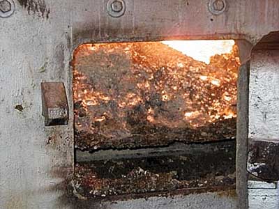
Within the confines of a coal plant, the areas most vulnerable to coal dust explosions are the coal silos and tripper bays. There are several reasons for these vulnerabilities. Both areas are downstream of the plant’s coal crushers, which increase the amount of fines in the incoming coal stream. For tripper bays, conveyors are the primary source of coal dust. In the case of silos, the process of filling them up generates lots of airborne coal dust.
If coal dust is present in the air in sufficient concentration, any of several sources — a static charge, hot metal parts, a spark, or a flame — can ignite the dust and cause an explosion. Under certain circumstances, coal dust can even explode on its own — a process called spontaneous combustion.
Tripper Bays and Silos
The tripper bay houses the conveyor system and machinery used to bring coal from the crushers to the silos. One or more trippers may travel the length of the bay to deposit coal into its silo.
A tripper bay above one or more silos is a typical plant configuration. For environmental reasons, the tripper bay usually is enclosed in a building, which makes the bay’s design more challenging.
When an explosion occurs in a silo, it always vents into the tripper bay. The top of the silo is either level with the tripper bay floor or slightly recessed (Figure 3). To minimize transport of airborne dust, the silo fill openings at the tripper bay floor generally are covered with rubber seals or flexible rubber belts. The seals or belts are mechanically opened or moved as the tripper processes the fuel. On recent Bechtel Power projects, angled fill chutes have been used to allow continuous travel of the tripper while filling the silos (Figure 4). These chutes are interconnected at the tripper floor.

3. A typical silo and tripper bay configuration. Source: Bechtel Power Corp.
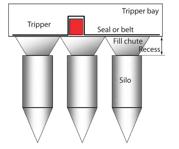
4. A typical silo and tripper bay arrangement for a continuous-feed system. Source: Bechtel Power Corp.
Typically, the silo feed rate is set at about three times the burn rate of the boiler, to allow a 24-hour fuel supply to be replaced in eight hours. Silos designed to house Powder River Basin (PRB) coal are usually cylindrical in design with conical hoppers, as recommended by NFPA 850 5. The silo’s slope is typically 60 degrees or greater, with respect to horizontal.
A 60-degree angle is sufficient to support "mass flow," which minimizes coal bridging and the creation of voids within the stored coal. If a bridge is created, it can produce a sudden drop in the fuel bed when the silo is emptied. Such an event can create dust clouds of explosive concentration in the silo. Designing for the mass flow condition helps minimize the residence time of the coal; the less time it spends there, the lower the likelihood of spontaneous combustion.
Coal Size and Explosion Control
The size of the coal exiting the crusher depends on how it was handled before reaching that point. After crushing, the largest pieces of the coal — its top size — are usually from 1¼ to 1½ inches in diameter. The bulk of the coal is generally less than ½ inch across.
Test data from one particular crusher indicate that 60% to 70% of its output is less than ¼ inch in diameter. A conservative estimate is that the flow from the crusher could contain 3% to 5% dust — particles 420 microns and smaller.
Lorum ipsum pullis quotum canecta django reinhart lonesta booma piero umiliani mario baba ennio morricone. Canecta django reinhart lonesta booma piero umiliani mario baba ennio morricone piero umiliani mario.
Collecting dust both where the crusher discharges to the conveyor and where the conveyor unloads to the tripper reduces the amount of fines in the stream entering the silo. Doing so at these locations is also most efficient. However, some dust always will be created and spilled by the conveying process, and it must be captured by rigorous housekeeping.
NFPA 68, which became a standard in December 2006, provides detailed guidance about the design of "deflagration explosion venting" of various gases, dusts, and mixtures that are not subject to explosion by detonation. The standard addresses how to design the venting after it has been determined that it is needed.
NFPA 68 has two overall goals: to protect personnel to the extent practical and to limit property damage to the extent determined reasonable by hazard analysis. Specifically, the standard aims to:
-
Prevent ruptures of unoccupied enclosures vulnerable to deflagration explosions.
-
Prevent structural failures of enclosures containing personnel, and minimize injury to personnel outside them.
-
Arrange venting discharge to prevent injury to personnel.
-
Limit damage to vented enclosures.
-
Avoid damage to adjacent property or structures due to blast pressure, projectiles, or ignition.
The general equations used for designing explosion venting for low-strength building enclosures and for high-strength process vessels are similar. However, the design limits and the methodologies used in the analyses may be different. Accordingly, it is essential to know the composition of the coal being used at the plant as well as the design pressure limits of the relevant enclosures.
For example, when using the equations it’s important to know that the term "minimum explosive concentration" (MEC) represents the minimum concentration of dust in air that’s required to propagate a deflagration. Generally, airborne concentrations of 25% or less of the MEC are considered safe.
Construction Criteria
Depending on how silos are vented, the design pressure for large silos can reach upper limits of around 2,500 to 3,000 lb/ft2. As a result, the silo’s fill chute, vent ducting, and other connections to it must be designed to withstand that pressure.
Vent ducts should be kept as short as practical to limit the pressure that flow resistance within them would cause to be applied to the silo. Meanwhile, the closure system over the silo fill chute and explosion vent should be of lightweight construction, to minimize a similar pressure effect on the silo — this one due to inertia of the vent closure.
Enclosed building structures for the tripper bays should be designed to withstand a minimum design pressure of 100 lb/ft2. However, higher pressures may be required, depending on the static vent’s release pressure and the design code being applied.
Essential Requirements
The potential for a coal dust explosion at a power plant is not something to take lightly. In fact, as more utilities switch to PRB coal to meet tighter SO 2 emissions standards, the number and frequency of coal dust explosions are expected to increase, because PRB coal is more prone to spontaneous combustion than eastern coals.
With carefully engineered and maintained coal-handling and dust collection systems, power plants can indeed burn PRB coal safely. A comprehensive housekeeping program also is essential to making coal dust explosions rare occurrences.
Be aware that power plants that switch to PRB coal may not be adequately designed to handle coal dust explosions. The higher deflagration index (KSt) value associated with PRB coal will produce relatively higher explosion pressures in silos. For this reason, PRB coal silos require comparably greater vent area for buildings.
As the mechanic in that old TV commercial for expensive, top-quality motor oil explained, "you can pay me now, or pay me later." The moral applies equally well to handling PRB coal safely. The cost of a well-designed coal-handling system — whatever its price — will always be less than the cost of repairing damage to equipment caused by a coal dust explosion.
— This item is based on a paper presented by Bechtel Power Corp.’s Brian Meaton; Vincent C. Ionita; Luis M. Moreschi, PhD, PE; David M. Nieman; and Cleveland B. Skinker, PE, at the 2007 PRB Coal Users’ Group meeting.