New environmental regulations have forced many coal power plant operators to consider alternative options for handling their boiler bottom ash. Although mechanical drag systems can often meet regulatory requirements, space can pose problems and costs can be significant. An innovative grinder-conveyor design offers a number of advantages over more-traditional systems.
New and pending federal regulations for coal combustion residuals (CCR) storage and handling are driving many coal-fired power plants to convert to new technologies for bottom ash transport. Plants in the U.S. have traditionally sluiced bottom ash to surface impoundments in which the solids settle out. U.S. Environmental Protection Agency (EPA) regulations aim to mitigate the environmental risks associated with long-term storage of ash in impoundments as well as the discharge of transport water from the impoundments. The EPA’s Disposal of Coal Combustion Residuals from Electric Utilities rule has already forced many plants to convert their ash handling systems in order to meet the minimum criteria established by the rule for such impoundments.
Effluent Limitations Guidelines (ELG) may drive another wave of conversions, although the regulation is currently on hold for bottom ash transport water while the EPA considers a revision for this stream and flue gas desulfurization system wastewater. If upheld as proposed, the ELG would establish a zero-discharge requirement for bottom ash transport water, which would effectively prohibit the use of surface impoundments altogether for bottom ash.
Mechanical Drag Systems
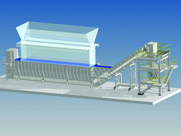
At the time of issuance of these rules, several technologies had been developed by industry original equipment manufacturers (OEMs) to accommodate landfill of bottom ash in lieu of surface impoundment. One such technology is a mechanical drag system placed directly beneath the boiler in which bottom ash falls into a water-impounded trough hopper with a chain conveyor at the bottom (Figure 1). In this system, the water acts to quench and fracture the hot ash while the conveyor drags the ash up an incline to drain the water. The resulting damp ash can then be transported to landfill. This technology had been around for years and was preferred for new-build plants in the more-recent past.
 |
|
1. Conventional mechanical drag system. Courtesy: Babcock & Wilcox |
In the ELG, the EPA identified two technologies—a mechanical drag system or a remote mechanical drag system—as the best available technology (BAT) economically achievable. The EPA cited the need to include the remote system option due to potential space constraints at some plant boilers, recognizing under-boiler mechanical drag systems to be large and intrusive as a retrofit to established plants. Indeed, most plants could not fit the large conveyors without major construction work due to structural steel, coal mills, air ducts, steam pipe, and other equipment in the area. Further, bottom ash hoppers are often located in a sub-grade pit, making retrofit of a conventional drag system nearly impossible. Even in the few instances where these conveyors could be retrofit, construction costs were high due to the work involved to essentially remove and replace the large bottom ash hopper.
The remote drag technology was developed specifically for the market created by the new regulations. Its value is that the bottom ash hopper and hydraulic sluice system beneath the boiler remain essentially untouched while drag chain conveyors are installed at a location remote from the boiler area in the plant yard. Instead of sluicing the bottom ash slurry to ponds, flows are diverted to the remote conveyors, where the solids are settled and dewatered similar to the under-boiler conveyors. However, a key difference with the remote system is that all the water in the system is defined as transport water as opposed to quench water, and transport water is subject to a zero-discharge requirement per the proposed ELG. This means that all water in the system must be recirculated, which substantially increases capital, and operations and maintenance (O&M) costs.
Since release of the ELG, plant owners and operators have made it clear that wherever possible, under-boiler systems are preferred, in large measure to avoid the liability associated with using transport water in the remote systems. Nevertheless, most of the early conversion projects were remote systems due to the space constraints previously mentioned.
Grinder-Conveyor System
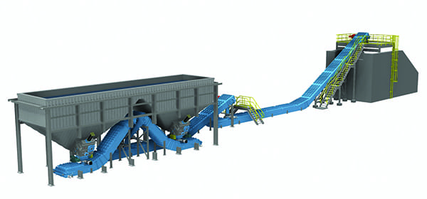
With the disadvantages of the two identified BAT options being evident, a new technology emerged after the release of the ELG in which under-boiler chain conveyors would fit beneath the existing ash hoppers (Figure 2). This technology serves as a solution to the problem of space restrictions and high installation costs associated with the conventional under-boiler mechanical drag system while still avoiding the use of transport water and zero-discharge requirements. In the last couple of years, it has gained acceptance and has proven successful on three operating units with an additional two currently under construction.
 |
|
2. Grinder-conveyor system. Courtesy: Babcock & Wilcox |
A critical and distinguishing feature of the new conveyor system is that a clinker grinder is used to crush the ash prior to feeding into the conveyors. These are the same types of grinders used in the sluice systems to reduce size prior to pipeline transport. In many cases, the old grinders can be retained in place along with the ash hopper and gate when the new conveyor system is installed.
The grinder is a key feature for retaining the hopper. Because there are usually only a few feet of headroom beneath the hopper, the conveyors must be small. Conventional under-boiler drag chain conveyors are large to allow sizeable clinkers to be removed without crushing. But with the new grinder-conveyor system, the conveyor housing only needs to be sized to meet the required volumetric removal rate rather than being sized to pass a single large clinker. A typical profile of a grinder-conveyor housing is about two feet high by two to three feet wide.
Both the conventional and grinder-conveyor drag chains have parallel strands of chain with steel flights spanning the strands to push ash along the travel path. Once the ash has been elevated to the top of the incline, it dumps into a chute while the chain and flight assembly turns 180-degrees around a head sprocket and progresses back down the incline and toward the tail end of the conveyor in an endless loop.
The conventional conveyor is known as top-carry because the run of chain transporting the ash is above the return run with the floor of the submerged hopper separating the two. The return run is called “dry” because it is not within the submerged bath of water. This arrangement necessitates that the chain elevates above the water level in the hopper at both the head and tail ends. Considering that the water level is typically about 15 feet above the ground floor, and allowing for some travel distance above the water on the incline for dewatering, it can be appreciated that such a system is difficult to retrofit in a congested plant.
The addition of a grinder in the grinder-conveyor system permits the conveyor to remain below the water level at both the head and tail. This provides the flexibility to transfer to a subsequent conveyor under water and arrange a train of conveyors to remain at low elevation until a clear space is reached to elevate above the hopper water level, which is typically done with the final conveyor at the disposal bunker outside the boiler building.
The grinder makes this possible because the chain conveyor can be configured to be bottom-carry with the return run traveling above the carry run within the water bath. Because the ash has been crushed, it can pass through the return run which is supported only under the chain with the flights hanging in suspension, meaning there is no floor separating the carry and return runs. This creates a fully enclosed conveyor with the added benefit of eliminating spillage of water and residual ash sticking to the flights in the return run, which is a nuisance of both the conventional under-boiler and remote conveyors.
The grinder-conveyor design also provides routing flexibility to work around existing obstructions in the boiler area. Often the most direct route from the grinders to the preferred storage location is obstructed by structural columns or coal mills. But because the conveyors are loaded at individual points rather than along the entire axis of the furnace hopper, as with the conventional conveyors, grinder-conveyors can be oriented in any direction necessary. So, while the most direct method is to use a common conveyor to collect from multiple grinders, there is flexibility to use a unique conveyor beneath each grinder and then transfer to a common. Furthermore, the ability to “turn” a conveying train by rotating at a submerged transfer point provides many routing options to avoid existing equipment.
Redundant Options
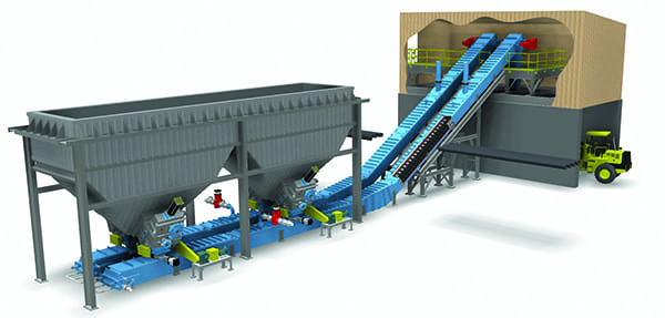
Another attractive feature of a grinder-conveyor system is that redundancy can often be built into the conveyor layout. For ash hoppers with dual grinders on each of the pant-legs, a grinder-conveyor can be installed to pick up all grinders on one side of the pant-legs and a separate 100% capacity conveyor can be installed beneath the other set (Figure 3). This is not possible in the conventional under-boiler design with its single conveyor at the bottom of the integral trough hopper, which requires a unit outage to repair a chain break or clear a jam in the ash collection area.
 |
|
3. Grinder-conveyor system with redundant conveyors. Courtesy: Babcock & Wilcox |
Even if a single grinder-conveyor arrangement is used, most maintenance jobs do not require a unit outage, because the conveyors can be isolated from the ash hopper by closing the hopper gate above the grinder and closing a secondary isolation gate below the grinder. This allows the boiler unit to continue to run as ash is collected in the pre-existing ash hopper until maintenance is complete.
Plant operators who have selected the grinder-conveyor technology for their bottom ash conversion projects have primarily done so because of the substantial savings in capital expense (equipment and installation) afforded due to the design features that have been highlighted. O&M savings also can be substantial when compared to competing technologies that either sluice to remote dewatering equipment or pneumatically convey the ash dry to a storage silo. Pumps and blowers used in these systems are high power consumers compared to chain conveyors. For example, comparing two recent projects at plants each with two operating units and similar MW output, the plant using the grinder-conveyor technology required only 10% of the installed horsepower as the plant that selected a remote mechanical drag system. Furthermore, eliminating the high-pressure sluice water can provide large savings on maintenance costs associated with pump rebuilds.
Coal plant owners and operators are continuously looking for ways to reduce cost to stay competitive. Closures and gas conversions have become common for plants facing steep compliance costs associated with new regulations. Grinder-conveyor technology for bottom ash conversions can offer significant savings in both capital and operating expenses, and allow existing coal units to remain operational in the face of such challenges. ■
—Tyler Little is an engineer in The Babcock & Wilcox Co.’s advanced engineering applications department.