Carbon capture and sequestration is very likely to be a key element of any future greenhouse gas legislation. Integrated gasification combined-cycle plants now under design have provisions to separate the CO2 at elevated pressures. Coal-fired plants have a far more difficult and expensive task — separating and compressing CO2 from pressures just above atmospheric conditions.
Any carbon capture and sequestration (CCS) system retrofitted to a typical pulverized coal (PC) power plant must pressurize a relatively pure CO2 gas captured from the exhaust to its supercritical liquid state before sequestering it underground in stable, geological formations. The challenge of implementing CCS on the scale likely to be required in the future will be to reduce the installed cost and minimize the operating cost penalties inherent to the processes.
(Conventional carbon capture technologies and their relative operating efficiencies and auxiliary power costs have been discussed at length in POWER: "Options for Reducing a Coal-Fired Plant’s Carbon Footprint: Part I," June 2008, and Part II, July 2008.)
Today’s CO2 capture systems were typically optimized as chemical processes that were usually disconnected from the CO2 compressors that are required at power plants. This means that CO2 compressor technology has incorrectly been considered a done deal rather than a technology opportunity that deserves more research and development.
How to Capture the Carbon
CO2 capture systems differ with power plant size and type. PC plant designs account for the vast majority of the existing power plant fleet and will figure prominently in the new construction mix going forward.
PC plants are typically designed with either an amine- or an ammonia-based CCS process. The amine processes generate a relatively pure CO2 gas stream, saturated with water within a 70F to 100F inlet temperature range at pressures of 15.0 psia to 21.9 psia. Ammonia-based capture processes can also generate a relatively pure CO2 stream, but at elevated pressures of between 30 psia and 300 psia; the inlet temperature is nominally 100F.
Both amine- and ammonia-based CCS systems must compress CO2 to a supercritical state for transportation and/or storage. Storage pressure local to the power plant will require a nominal 1,600 psia, while the current pipeline specification is 2,215 psia. The key to minimizing the variable operation and maintenance (O&M) costs of either CCS system is to integrate the most efficient and reliable compression technology with the capture process.
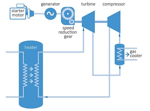
Ramgen Power Systems is developing a high-efficiency gas compressor using the same shock compression technology as is used by supersonic aircraft inlet systems (Figure 1). Shock compression is uniquely suited to compressing large volumes of CO2. This technology—funded by the DOE’s National Energy Technology Laboratory, with cofunding from Dresser-Rand — promises to significantly reduce gas compression auxiliary loads in CCS systems.
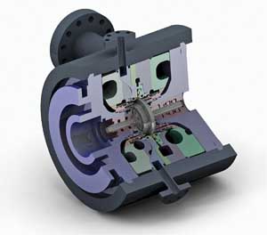
1. The Ramgen Power System HP-18 gas compressor. Source: Ramgen Power Systems LLC
Compression vs. Liquefaction
Either CO2 is compressed to the desired pressure using a gas compressor or is liquefied at lower pressures by using refrigeration systems and then pumped to the desired pressure. The underlying premise of the liquefaction approach is that liquid pumps require significantly less power to raise pressure and are considerably less expensive than gas compressors. Careful assessment of the refrigeration process is critical for accurate system power accounting.
To compare the shock compression technology compression efficiency, let’s consider a case study. First, we select a nominal 250 psia capture system discharge, because this is the nominal range of the ammonia processes and the typical interstage pressure in most of the amine-based compression processes. It is also the minimum pressure level at which liquefaction evaluations have been performed and one that best illustrates the difference between liquefaction and compression.
The case study operating conditions are typical of those expected in a retrofit carbon capture system for a coal-fired power plant. In this study, we’ll compare the power requirements for gas phase compression of CO2 from 250 psia to 2,215 psia versus CO2 liquefaction at 250 psia and pumping that liquid CO2 to 2,215 psia.
Neither of these options includes the low-pressure (LP) compressor section, as that horsepower requirement is assumed to be same for both options. We will estimate the LP compressor options later in this article. The gas is also assumed to be intercooled after the LP stage discharge, as is normally the case in either of these options.
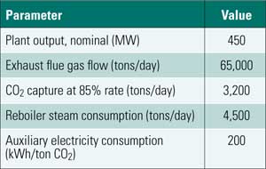
For purposes of comparison, we assume the initial ambient conditions are 100F and dry. Cooling water is assumed at 85F, if used. The CO2 gas mass flow is 517,475 lb/hr, or the equivalent of 90% capture on a 300-MW coal-fired power plant, burning Illinois #6 coal with a heat rate of 9,441 Btu/kWh (Figure 2).
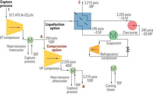
2. Compare the alternatives. This flow diagram illustrates the typical compression process (A to B) and the typical liquefaction process (A to C) as design alternatives for a carbon capture system. Both processes begin with a low-pressure compressor and heat-recovery intercooler (1 to A). Source: Ramgen Power Systems LLC
Gas Compression Option. Ramgen would suggest a single-stage compressor with an 8.9:1 pressure ratio sized for the specified flow (see sidebar: "Low-Cost, High-Efficiency CO2 Compression"). The compressor would have a nominal rotor diameter of 18 inches.
The enthalpy change across the compressor is 75.85 Btu/lb of CO2, which equates to an input compression power of 15,427 hp at the reference gas mass flow. Gas properties are calculated using subroutines provided by NIST REFPROP 7.0. Mechanical losses are estimated as 477 hp (3%), resulting in a total shaft power requirement of 15,904 hp (11,857 kW).
There is also an option of some heat recovery from the high-pressure (HP) compressor discharge, although it is not included in this comparison. The heat-recovery potential is 172 Btu/lb of CO2 between the 485F discharge temperature and 100F.
Liquefaction Option. The liquefaction option has two power loads that must be considered: the refrigeration compressor and the cryogenic pump. We will first calculate the load for the refrigeration compressor.
The refrigeration cycle evaporator has both an effectiveness and a pressure drop that must be accounted for. CO2 passing through the evaporator is assumed to encounter a 5 psi pressure drop which, when added to an additional 5 psi drop in the economizer, necessitates a 240 psia liquefaction pressure and an associated –13.9F liquefaction temperature. A typical heat exchanger approach temperature is 10F, and cryogenic pump manufacturers typically specify a minimum of 15F subcooling to avoid pump cavitation, so both the CO2 and the exchanger cold-side temperature must be reduced by an additional 15F. This results in a CO2 temperature of –28.9F and a cold-side temperature of –38.9F. We have used these values for calculating the liquefaction refrigerant load.
The enthalpy of CO2 at 100F and 250 psia is 216.02 Btu/lb; at –28.9F and 240 psia it is 53.98 Btu/lb. Therefore, the specific work to liquefy CO2 is 162.04 Btu/lb, equivalent to 83.85 million Btu/hr or 6,987 tons of refrigeration at 517,475 lb/hr of CO2. The power is calculated based upon a 10F approach temperature and a water-cooled condenser operating on 85F cooling water consistent with the gas compression option.
R-22 has been assumed as the refrigerant for purposes of calculating refrigeration load. We recognize that this refrigerant is scheduled for phase-out, but it does serve as a useful basis for calculating and comparing the power required. R-134a could be used on the 800 psia case, but for consistency we elected to use R-22. Power consumption for the 800 psia liquefaction case is approximately 5 hp less if R-134a is used instead of R-22, so the differences are negligible for our purposes.
At the assumed operating conditions, the compressor adiabatic stage efficiency is calculated as 74%, per ASHRAE guidelines. We have used this stage efficiency at the 12.5:1 compression ratio required by R-22 at these conditions. At the liquefaction conditions described above, refrigeration efficiency is 2.003 kW/RT (kW per refrigeration ton), and the resulting refrigeration power required is 18,772 hp (13,998 kW). The refrigeration compressor efficiency for other operating conditions is scaled from a low of 72% at 220 psia to high of 83% at 800 psia and above (Figure 4).
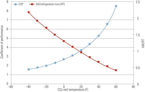
4. Below freezing. Typical efficiency and coefficient of performance (COP) for a CO2 compressor for a given compressor outlet temperature. Source: Ramgen Power Systems LLC [Note that the legend labels were incorrectly identified in the print version of this figure. COP and kW/refrigeration tons are correctly identified here.]
The second auxiliary load that must be considered for the liquefaction option is the cryogenic pump. Cryogenic pump hydraulic efficiency is assumed at 75% with suction conditions of –28.9F and 240 psia, discharging at –15.4F and 2,225 psia, allowing for a 10 psi pressure drop in the economizer. Enthalpy change is 7.12 Btu/lb, equivalent to 1,447 hp or 1,809 hp at the pump shaft, assuming parasitic loss is 25%.
An economizer can be added to the cycle to offset some of the refrigeration load and provide initial CO2 cooling by the cold cryogenic pump discharge. An economizer with approach temperature of 10F and a pressure drop of 5 psia was selected for this case study.
Economizer effectiveness is limited by the 10F approach temperature constraint, and therefore the enthalpy exchange is limited to 25.90 Btu/lb, resulting in an economizer effectiveness of 44%. The refrigeration load is thereby reduced from 162.04 Btu/lb to 136.14 Btu/lb. The refrigeration power is reduced to 70.50 million Btu/lb or 5,871 RT, requiring 15,773 hp — a savings of 2,999 hp. A comparison of the auxiliary power required for both compression options is shown in Table 1. The same analysis was completed with liquefaction pressures ranging from 220 psia to 900 psia (Table 2).
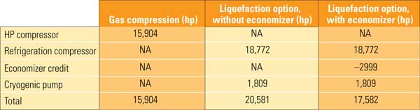
Table 1. Reducing CO2 compression power. Compressing CO2 from 250 to 2,215 psia with the Ramgen CO2 compressor is 9.5% more efficient than liquefying the CO2 and pumping it to pressure. These numbers do not include the LP compressor auxiliary power requirement that is common to both options (Figure 1). Source: Ramgen Power Systems LLC
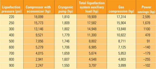
Table 2. Compression vs. liquefaction performance matrix. The compression auxiliary power advantage goes to gas compression at about 500 psi. These numbers do not include the LP compressor auxiliary power requirement that is common to both options (Figure 1). Source: Ramgen Power Systems LLC
Low-Cost, High-Efficiency CO2 Compression
CO2 compressors are responsible for a large portion of the enormous capital and operating cost penalties expected with any carbon capture and sequestration (CCS) system. The CO2 compressor power required for a pulverized coal power plant with an amine-based capture system is approximately 8% to 12% of the plant rating, depending on operating conditions.
A typical 1,000-MW coal-fired plant requires 120 MW, or 160,000 hp of auxiliary power costing upwards of $180 million for a 3 x 50% CO2 compression system using current technology. The CO2 compressor power required for an integrated gasification combined-cycle power plant is approximately 5% of the plant rating. A 600-MW PC plant will require 30 MW, or 40,000 hp, at an estimated $45 million for the same 3 x 50% compressor configuration. The higher-pressure ammonia-based processes consume about one-half of that power at less than one-half the cost, but that is still a considerable first cost and operating expense.
Existing CO2 compressor designs are expensive because the overall pressure ratio is 100:1 and, in part, because they require stainless steel construction to accommodate CO2 in the presence of water vapor. By far the most significant impact on cost is an aerodynamic design practice that limits the design pressure ratio per stage on heavier gases such as CO2.
Standard turbomachinery design practice is to limit the inlet flow Mach number at the stage inlet to avoid generating shock waves in the blade passages and their accompanying aerodynamic losses. This is typically done by adjusting the rotational speed. The Mach number itself is a function of molecular weight, and therefore the effect is more pronounced with heavier-than-air CO2. This speed limitation results in a pressure ratio per stage of approximately 1.7 to 2.0:1 on CO2. At these stage pressure ratios, eight stages of compression are typically required to reach an overall pressure ratio of 100:1.
Ramgen, on the other hand, designs its rotors to create and manage shock structures that can realize the full effect of shock waves to efficiently generate substantial pressure ratios. The Ramgen CO2 compressor concept achieves the required 100:1 pressure ratio in two stages of compression, each rated at 10:1. An intercooler is used between the LP and HP stage.
Ramgen’s compressor changes speed to achieve design pressure or head, following a line of constant specific speed. As the compressor speed is increased to achieve higher pressure ratios, the capacity of the unit will also increase. The power will go up, of course, but the unit can be one or even two sizes smaller (Figure 3).
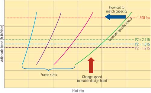
3. Pinpoint performance. Single-stage compressors are rated on rotor diameters.The operating speed of a single-stage unit is adjusted within mechanical limits to meet the head or pressure required, and the frame size is determined by the capacity required at that operating speed. Source: Ramgen Power Systems LLC
An additional benefit is that stage discharge temperatures range between 450F and 500F, depending on inlet gas and cooling water temperatures. This offers the opportunity for process heat recovery, without compromising compressor performance. Potential uses for the heat recovered in both the intercooler and aftercooler include regenerating amine solutions or preheating boiler feedwater. Also, in a CCS application, the capture process itself may become the intercooler and aftercooler to further improve the overall process efficiency.
Remember, as the compressor stage is driven faster, it produces significantly more flow, and the rotor size can be reduced for a given capacity. In practical terms, if the HP stage is rated at the full 2,200-psia nominal discharge pressure, the rotor will run faster and is likely to be one to two sizes smaller than it would be if it were rated at 1,200 psia. The associated first cost savings are significantly more than the cost of the cryogenic pump that would be required to boost the pressure from 1,200 psia to 2,200 psia.
LP Compression Options
As noted earlier, neither of these compression options includes the LP compressor auxiliary power, as that power has been assumed to be the same regardless of the high-pressure compression option selected (see Figure 2, process 1 to A). As an example of the magnitude of the LP compressor auxiliary power required, consider the extreme case of an 800 psia liquefaction pressure. That choice will require a conventional, six-stage integrally geared compression unit, estimated to require 26,413 hp or a Ramgen LP and intermediate pressure (IP) set of stages of comparable power to reach the 800 psia liquefaction level, a 3,000 hp chiller, and a 1,600 hp pump. The total power consumption of this configuration would be 30,961 hp.
The power consumption for the liquefaction option at 800 psia is 94.7% of the compression option, but the absolute value of the power consumption difference between compression and liquefaction from 800 psia to 2,215 psia is only 255 hp, as shown in Table 2. The added complexity to support a refrigeration loop may not be attractive in view of the minimal savings, elevated ambient temperatures, and system complexity.
Other low-pressure compression options are available. A typical two-stage configuration operating at 800 psia will require 35,840 hp with an exit temperature of 500F. Similarly, a three-stage configuration, designed for equal pressure ratios per stage, will total 30,625 hp with a 350F exit temperature from the third stage. The reduced auxiliary power does come with a price: The first cost of the three-stage unit is 35% higher than for the two-stage alternative.
Ambient temperature also has a pronounced effect on compressor performance. The analysis so far has assumed 85F cooling water, typically from a cooling tower. In higher ambient locations, or in locations where an air-cooled condenser is required, the break-even point shifts more in favor of the compressor option. An increase of 10F, from 85F to 95F, at a 250 psia liquefaction pressure almost doubles the compression power savings shown in Table 2.
—Peter Baldwin (pete_baldwin@ramgen.com) is president, and Joseph Williams is chief engineer for Ramgen Power Systems LLC, Bellevue, Wa.