Only through proper troubleshooting and then solving the underlying problems can control loop performance be improved. Process design certainly plays a role in control loop performance, but experience has shown that the majority of control loops can perform better—provided that the root cause of the poor performance is found and corrected.
Most power plants have a few control loops that never seem to control satisfactorily. These loops may oscillate for seemingly no reason or deviate far from their set points during load ramps and disturbances, often overshooting their set points afterward. Tuners can spend many hours trying to tune these challenging control loops, but the loops often remain problematic.
Poor control performance makes itself evident primarily when a controlled variable (process variable) deviates excessively from its target value (set point). Excessive and/or unnecessary deviations from set point can result from oscillations, sluggish control loop response, and excessive measurement noise. Each of these can have several causes (Table 1).
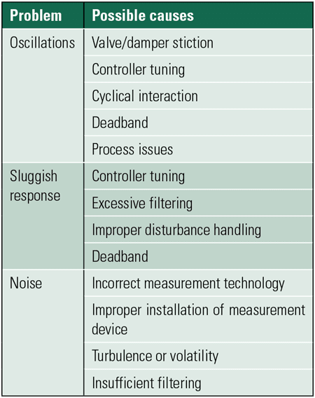 |
| Table 1. Common problems and possible causes of poor control performance. Source: OptiControls |
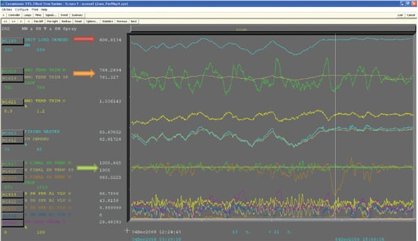
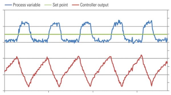
Oscillations are periodic deviations from set point, frequently intermixed with some random behavior (Figure 1). Sluggish response is a general slowness in the loop’s ability to recover from disturbances or follow set point changes. Noise is random movement in the process variable. For more information on using performance-monitoring software to improve loop performance, see my earlier article, “Monitoring Control Loop Performance,” in the February 2012 issue, available at https://www.powermag.com.
 |
| 1. Random moves. Oscillations are cyclical deviations from the set point and often contain a component of randomness. Other control response problems include sluggish response and noise. Source: OptiControls |
Troubleshooting Oscillations
Oscillations can originate from within the control loop or may be caused by external factors. Oscillations may also be a result of a cyclical interaction between two or more control loops. To narrow down the possible causes of the oscillation, the controller should be put in manual mode to see if the oscillation stops. If the oscillation persists when the controller is in manual mode, the oscillation originates from outside the loop. Oscillation analysis of interacting loops and equipment should then be done to find the root cause. For example, steam generator furnace pressure can oscillate because of a partially blocked rotating air heater.
If a control loop’s set point oscillates, it will most likely cause the entire loop to oscillate. The cause of oscillations should be traced back to the origin of the loop’s set point. For example, if a desuperheater outlet temperature control loop oscillates because its set point is oscillating, the problem likely lies with the main steam temperature controller producing the set point. To verify this, put the main steam temperature controller in manual and see if the desuperheater outlet temperature controller stops oscillating. If it does, troubleshooting should be focused on the main steam temperature controller.
Interactions Causing Oscillations
There are three principal factors that trigger oscillation of boiler control loops: interaction between loops, stiction, and deadband.
Cyclical Interactions. Tightly coupled boiler control loops with similar dynamics can begin to oscillate against each other. A good example of this is feedwater flow controlled with a variable-speed pump and differential pressure controlled with a feedwater control valve. The pump and valve each affect both the flow and the pressure, and a cyclical interaction between the flow and pressure control loops can easily occur. Cyclical interaction can be aggravated by aggressive tuning, for example when using quarter-amplitude-damping tuning methods, such as the Ziegler-Nichols or Cohen-Coon tuning rules without reducing the calculated controller gain by at least 50%.
The simplest technique for solving problems with cyclical interactions is to tune one of the interacting control loops to produce an overdamped response. The IMC (Lambda) tuning method can be used to obtain very stable control loops and has been proven to help settle down cyclical interactions.
Because a boiler consists of many interactive sub-processes, one oscillating loop can cause several other loops on the boiler to oscillate with it. The loops will all oscillate with the same period of oscillation. Historical trends or process analysis software can be used to identify all the loops on a boiler oscillating with the same period. The problem loop can be isolated through knowledge of the boiler and its interactions, by looking at phase shifts between oscillations, or by placing likely culprit loops in manual one at a time.
For example, an oscillating reheat steam temperature control loop can cause oscillations in the generator load, throttle pressure, fuel, and drum level controllers. If the reheat temperature controller is put in manual control mode, the oscillations in all loops will cease. The reheat temperature control loop should be analyzed further. Note that this scenario is different from cyclical interactions in which two or more control loops interact directly with each other in a cyclical fashion. In the case of a cyclical interaction, any one of the participating control loops put in manual will cause all loops to stop oscillating.
Stiction. One of the leading causes of oscillations is stiction, short for static friction. When there is stiction, the final control element (for example, the control valve or damper) is mechanically sticky. The combination of a controller’s integral action and a sticky control element causes an oscillation called a stick-slip cycle (Figure 2). When loop oscillations are caused by stiction, the controller output’s trend often resembles a saw-tooth or triangular wave, while the process variable may look like a square wave or an irregular sine wave.
 |
| 2. Example of a stick-slip cycle. Source: OptiControls |
Stiction can be detected by placing the controller in manual mode and making small changes (typically 0.5%) in controller output followed by monitoring the process variable for a resulting change. If the control valve seems to accumulate a few of the controller output changes before the process variable responds to them all at once, the control valve has stiction.
Deadband. Deadband in a final control element is a mechanical defect causing a dead zone through which the controller output must change before the control element responds after a change in travel direction. Many control systems also provide an adjustable deadband around a controller’s set point. The latter is sometimes used to prevent the controller from reacting to process noise.
If an integrating control loop, such as mill or feedwater heater level control, drives a valve or damper directly, and the valve has deadband, the loop will oscillate. An integrating control loop will also oscillate if the controller has a deadband feature that is set wider than the measurement noise band.
Both kinds of deadband also reduce the effectiveness with which a controller can eliminate disturbances. Every time the direction of a disturbance changes, the process variable has to traverse the internal deadband before the controller begins responding, and the controller output has to traverse the controller’s final control element’s deadband before the latter actually begins moving. This causes the control loop to perform sluggishly. The speed of tuning should never be increased to compensate for deadband, because the aggressive tuning remains active after the deadband has been traversed, which can cause stability problems. Deadband in final control elements can severely affect the accuracy of controller tuning, often resulting in overly aggressive tuning.
Deadband can be detected with a simple process test consisting of two controller output steps in one direction and one step in the opposite direction with the controller in manual mode (Figure 3). The second and last steps should be the same size to make it easy to visually detect deadband from process trends. If the process variable does not reach the same level after the first and third steps, it indicates the presence of deadband. Final control elements with deadband must be repaired for optimum control.
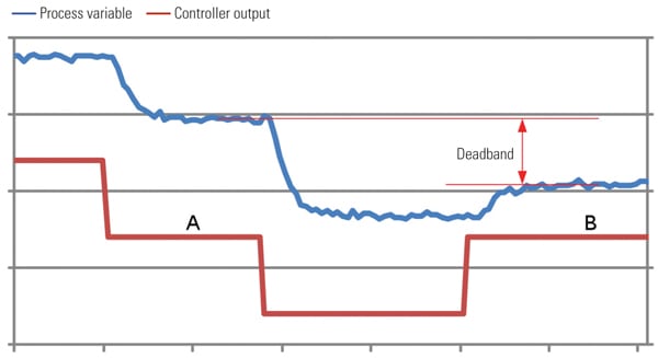 |
| 3. A deadband test. At time-slice A and B the controller output is at the same level. Because of deadband, the process variable does not return to the same level. Source: OptiControls |
Tuning Control Loops
Incorrectly tuned control loops can respond sluggishly, or they can overshoot and oscillate significantly. Controller tuning is often done in a trial-and-error way, but this is not nearly as effective as using tuning rules or software. Controller tuning should start with step tests on the process to determine the dominant process characteristics: process gain, dead time, and time constant. Four or more step tests should be done, the results compared, outliers eliminated, and the average used for tuning. If process characteristics change with unit load or operating conditions, gain scheduling should be used.
Note that using the IMC tuning method results in stable control loops, but it often leaves a sluggish response to disturbances, especially on slow loops like main steam temperature. Cohen-Coon tuning provides faster disturbance rejection, even with the detuning recommended earlier. Quarter-amplitude-damping tuning methods should not be used because they result in marginally stable loops and oscillatory plants.
When tuning control loops, it is important to understand that any control loop can hypothetically be tuned for a slower response, but that is not always the case for a faster response. As a controller is tuned for a progressively faster response, the control loop’s stability is compromised, and after some point it begins oscillating (Figure 4). A control loop’s settling time is therefore limited to a certain minimum. No control loop recovering from a disturbance or responding to set point change can settle out faster than this minimum settling time.
 |
| 4. Tune for response, not speed. A control loop becomes less stable and more oscillatory with increasing speed of response. Source: OptiControls |
The minimum settling time is virtually equal to the natural period of the process being controlled. It will take a control loop at least as long as the length of its process’s natural period to settle out after a disturbance or set point change. The natural period of a process is determined mostly by its effective dead time, but the amount of lag (time-constant) also plays a role (Table 2).
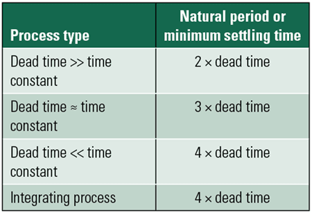 |
| Table 2. Natural periods of different process types. Source: OptiControls |
Control loops cannot effectively respond to disturbances or set point changes shorter in duration than the loop’s natural period (or settling time). Although correct tuning methods can go a long way in minimizing the effects of disturbances, if a disturbance occurs faster than the control loop can respond, there is very little the controller can do to reduce its amplitude. Then cascade and feedforward control should be considered.
Noise in Control Loops
Because noise-based deviations occur faster than the loop’s settling time, it is impossible for the controller to eliminate the noise or even reduce its amplitude. Furnace pressure, with its rapid deviations because of turbulence and unstable combustion, is a good example of this. A controller responding aggressively to noise will likely increase variability. It will also cause unnecessary wear on the final control element, and it may disturb downstream control loops.
Assuming the correct measurement technology is being used, and the measurement device is properly installed, the amplitude of noise can often be reduced through filtering the process variable with a first-order lag filter. The filtering should be applied inside the control system (not in a replacement transmitter), either as a setting on the analog input card or in the controller itself. It is important to note that a filter increases the effective dead time in a control loop and therefore increases its minimum settling time. A filter can also hide real process problems and unsafe conditions. Therefore, filtering should be applied only when needed, and then as little of it as possible.
— Jacques F. Smuts, PhD, PE (jsmuts@opticontrols.com) is the founder and principal consultant of OptiControls. He has more than 20 years of experience in process control, has trained hundreds of engineers and technicians in the field of process control, and is the author of the book Process Control for Practitioners.