A new boiler master concept combines the benefits of throttle pressure firing (return to the throttle pressure setpoint) and drum pressure firing (dynamic stability). It consists of a throttle pressure controller (reset action plus feed-forward signal) working in parallel with a drum pressure controller (proportional and derivative action). Because they are separated in the time domain, the controllers do not interact. This approach has proven particularly effective at stabilizing the operation of boilers equipped with low-NOx burners.
The new arrangement is much more stable than traditional throttle pressure firing. It has been successfully deployed on several units and should be of great interest to owners of subcritical coal-fired units because it offers a quick and inexpensive solution to pressure stability problems. Following a discussion of the new boiler control strategy, this article presents three studies detailing its installation at four coal-fired units owned and operated by the Kentucky Utilities (KU) subsidiary of E.ON U.S.: The 495-MW Unit 3 of E.W. Brown Generating Station; the 75-MW Unit 3 of Tyrone Generating Station; and the 75-MW Unit 3 and 100-MW Unit 4 of Green River Generating Station. Coal-fired plants produce about 95% of Kentucky’s total generation.
Time for a change
The strategy for the new boiler master combines several well-known approaches to control developed by Burns and Roe and others over the past 20 years. In 1985 we thought we had found the perfect solution with the Direct Energy Balance (DEB)-400 control strategy. However, problems quickly developed. After Leeds & Northrup went out of business, DEB-400 could not be replicated easily or legally on other distributed control system (DCS) platforms.
Burns and Roe began searching for a simpler firing rate strategy that would:
- Use drum pressure as a process variable, as a way of capturing most of the DEB benefits.
- Be portable to any DCS platform.
- Be easy to tune, reliable, and inexpensive.
Something old, something new
The idea of using the boiler drum as a calorimeter has been practiced commercially since at least 1957. Basically, this approach uses the derivative of the drum pressure as an excellent real-time indicator of the required heat input to the boiler (see box).
Going even further back, prior to the development of superheaters, all boilers were controlled by drum pressure. The boiler master of old was basically a proportional plus integral (P+I) drum pressure controller, and it worked very well.
Marine boiler control systems built in the 1950s are a good example of robustness. Most were pneumatic systems with a P+I drum pressure controller assisted by a steam flow feed-forward signal. The boiler master drove the fuel oil control valve directly, without the benefit of a fuel flow measurement. There was no gain compensation for the number of burners in service. All firing rate errors had to go through the process (that is, drum pressure upset). It was a fairly crude setup, but, nevertheless—because of the robustness of the drum pressure signal—this arrangement supported an amazing ramp rate of over 200% of the unit’s maximum continuous rating (MCR)/minute.
There’s a good reason why most boilers are still fired by throttle pressure: Throttle pressure is the final, visible product. It is what impacts steam turbine performance. Drum pressure is an intermediate result; the control system has to stabilize and maintain throttle pressure as constant as possible.
Throttle pressure equals drum pressure minus piping losses (losses vary as a square of the steam flow). Ideally, dynamic stability is maintained using drum pressure in real time while applying steady-state correction for throttle pressure. Dynamic stability is not hard to achieve when using drum pressure control. The problem is how to implement the necessary correction for throttle pressure without introducing dynamic instability.
New boiler master basics
The boiler master uses a throttle pressure controller for steady-state/slow responses and a drum pressure controller for dynamic response and anticipation. It consists of the following:
- A feed-forward signal (a function of the steam flow, calibrated for the number of mills in service).
- A bias from the throttle pressure controller (reset action only, applied to error).
- A bias from the drum pressure controller (proportional and derivative action only, with the derivative applied only to changes in pressure or volume).
Because significant derivative action from the drum pressure was used, some sort of output dampening was required. A moving average algorithm of 18 to 30 seconds duration was found to work best.
Experience has shown that above 90% of MCR, the drum pressure controller tuning must be slowed down or opacity spikes could result. The drum pressure controller’s proportional and derivative action is tuned adaptively, as a function of the unit’s output.
The airflow controller’s proportional and reset action also is tuned as a function of unit output, but as an additional measure to ensure steady combustion. As the unit approaches full load, each controller’s tuning becomes progressively less aggressive. The airflow control setup is fairly conventional; the controller’s setpoint is a function of steam flow.
A characterized steam flow-feed forward was also added as a belt and suspenders. In essence, the total demand of the forced-draft (FD) fan is a function of steam flow plus or minus the correction from the airflow controller. A feed-forward kicker (positive only) from the boiler master to total FD fan demand was used initially but proved unnecessary.
In the firebox
A conventional furnace oxygen control design was also selected. The airflow controller’s output is biased +/–20% by the oxygen controller. The oxygen controller’s setpoint also is a function of steam flow. The oxygen controller’s proportional, derivative, and reset actions are adaptively tuned, as a function of steam flow.
Low furnace oxygen levels (<0.5%) will cause a blocking action of raise/lower pulses to the speed changer motor and a fuel runback (automatic/manual station output) at a 1% per minute ramp rate. The fuel runback will stop at 3% oxygen and place the station in manual mode.
Remote load dispatch also was considered for the design. A high ramp rate of MW output or steam flow, MW output exceeding an operator-set limit, or high opacity (>18%) will block the raise/lower pulses to the speed changer motor. NOx and opacity measurements are used to minimize NOx production while maintaining an acceptable opacity level. The goal was to reduce NOx charges by one dollar per MWh, on average.
Case study 1
Kentucky Utilities’ E.W. Brown Generating Station (Figure 1) in Mercer County has three coal-fired units with a total capacity of about 750 MW. Unit 3, rated at 495 MW, is the largest of the three.
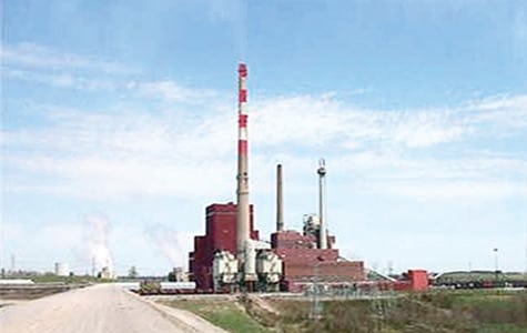
1. Stable response. A new boiler master design improved the stability and response of Unit 3 of E.ON U.S.’s E. W. Brown Generating Station. Courtesy: E.ON U.S.
After being retrofitted with a number of low-NOx control enhancements to meet Clean Air Act requirements, the unit began to suffer a noticeable increase in firing system lag time and degraded dynamic loading capability. The unit’s pressure was continually swinging by 100 psi in both directions even with the boiler master in manual. With the boiler master in automatic, swings of +/–200 psi were common. As a result, operators were constantly taking the boiler off load dispatch, with the expected negative impact on the plant’s bottom line.
The challenge was to evaluate the problem and propose solutions to enable the unit to remain on load control until a future DCS upgrade was completed. The approach was to run drum and throttle pressure controllers in parallel. To prevent interaction, the drum pressure controller was dedicated to real-time control and the throttle pressure controller was dedicated to steady-state control.
The boiler’s existing analog controls limited available hardware options, so a new boiler master was designed within the plant’s existing DCS-based data acquisition system. The patch was connected to the existing Bailey analog boiler control system’s current-to-voltage converters.
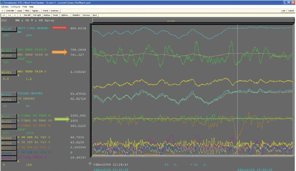
As mentioned earlier, the throttle pressure controller dominates steady-state/slow transients while the drum pressure controller provides most of the dynamic response and anticipation (Figure 2). Satisfactory response and stability were achieved with a long derivative time—three minutes. As operators gained confidence in the new control scheme, they stopped taking the boiler off load dispatch, increasing revenue.

2. Improvisation. The boiler master design that was used for E.ON U.S.’s E.W. Brown Plant Unit 3. Source: Burns and Roe
Case study 2
The traditional throttle pressure firing strategy had stopped working on Unit 3 of KU’s Tyrone Generating Station after a low-NOx retrofit. As a result, the unit had been run for years with the boiler master in manual. Even in manual, the unit was prone to load swings of +/–7% of MCR (+/–5 MW).
The same boiler master strategy developed for E.W. Brown Unit 3 was used with great success on Tyrone Unit 3. It was configured in the existing Bailey boiler control system.
Tests indicated that throttle pressure responded to changes in the boiler master with a lag of five to six minutes, most likely due to the large thermal storage of the unit (which has a relatively large drum) and the typically sluggish response of the low-NOx firing system. Satisfactory response and stability was achieved by using a drum pressure controller derivative time of five minutes.
Much care was taken in the selection of the reset action of the throttle pressure controller. Aggressive reset led to a quick recovery of throttle pressure but produced a significant throttle pressure roll. At the moment, reset timing of 0.04 repeats/minute is being used. This results in an acceptable 4-psi pressure roll, with 22 minutes between peaks.
Case study 3
The 75-MW Unit 3 and 109-MW Unit 4 of Green River Generating Station (Figure 3) had difficulty maintaining combustion control operation because optimal tuning of the their low-NOx burners could not be maintained. Because the burners were not integrated with combustion control, after being tuned for one set of operating conditions, they would quickly drift and require more tuning.
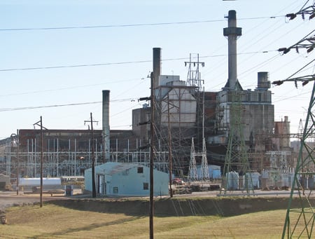
3. Twin projects. Significant heat rate reductions were the result of boiler master updates at E.ON U.S.’s Green River Generating Station. Courtesy: E.ON U.S.
KU’s Boiler Control Betterment Project for Green River Units 3 and 4 expanded on the successful implementation of the boiler master for their sister unit, Tyrone Unit 3. The strategy used at Tyrone Unit 3 only considered firing rate/throttle pressure stability, to ensure that the boiler control remained on automatic at all times. This was accomplished relatively easily and with great success. At Green River, an additional layer of a boiler master was added, along with layers of NOx optimization and adaptive opacity control.
Green River never had a proper furnace draft control because the units used FD fans to control furnace draft. The new boiler master transfers control of furnace draft to the units’ induced-draft (ID) fans. The units’ FD fan drives also were upgraded with smart positioners as a precaution. Because the units lacked sensors for measuring combustion airflow, multiple pitot tubes were installed in the secondary air ductwork.
The furnace draft controller has an operator-adjusted setpoint. Its proportional and reset action is adaptively tuned, as a function of steam flow. The controller also has a feed-forward signal that is a function of the total FD fan demand.
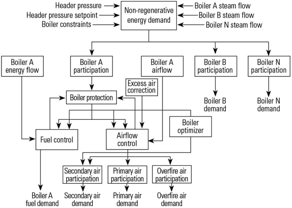
In contrast, the load controller at Green River is old and not integrated with the boiler control system. When opacity becomes a persistent problem and load must be reduced, that cannot be accomplished via the load controller. However, operators can disable pulses from the load controller using an external relay and, at the same time, reduce the throttle pressure setpoint by 50 to 75 psi. The load will drift down, and the opacity will be reduced. This feature is especially useful if the unit has already exceeded opacity once within the past hour. In such cases the load will be reduced, excess air increased, and load dispatch disabled until opacity can be reduced to an acceptable level (Figure 4).
4. Building blocks. The logic diagrams for the control modifications completed on E.ON U.S.’s Green River Unit 4. Source: Burns and Roe
As an additional measure to stabilize combustion, the throttle pressure controller’s reset action is adaptively tuned, as a function of throttle pressure error. As the error diminishes, the tuning becomes less aggressive.
Righteous results
At Green River, both units’ key performance results went in the right direction. Temperature and pressure control and unit response improved, while opacity excursions, NOx emission rates, and heat rates decreased.
The temperature controls reduced the superheat temperature swings on load changes from 50 degrees F to 20 degrees F on Unit 3, and from 60 degrees to less than 20 degrees on Unit 4. The side benefit has been reduced attemperation, which improves plant heat rate and reduces operator involvement—a good thing, given that the attemperation systems on both units have been very problematic for many years. Today, attemperator controls are run automatically virtually 100% of the time.
Unit ramp rates, a key measure of the responsiveness of a unit, increased from 1%/min to more than 3%/min without opacity, temperature, or pressure control problems. In addition, boiler stability improvements have greatly increased the amount of time the units spend on automatic dispatch control.
Perhaps the most visible improvements have been a reduction in the number of opacity exceedances. Green River has a stringent opacity limit of 20%. After the boiler master controls and combustion tuning were completed, exceedances on Unit 3 fell from 1% of operating hours to 0.13% with significantly less operator intervention. Although Unit 4’s historical opacity performance has been acceptable, the control retrofits have improved it while improving boiler performance.
NOx emissions also fell with the updating of boiler controls. Unit 3’s production of the pollutant declined by 9% (to below the burner manufacturer’s guarantee) and was attributed to the use of the NOx and opacity controller. In addition, NOx reductions at low load were extremely dramatic even though the boiler lacks access to a repeatable, accurate O2 measurement.
The most important performance metric for any thermal power plant is its heat rate. Unit 3’s heat rate decreased by more than 3% once the NOx controller began reducing excess air. As a result, the cost of the boiler control retrofit has already been paid for in reduced fuel consumption. The improvement in Unit 4’s heat rate has been even more dramatic: 5.4%, via the reduction of attemperation water flow and improved firing rate stability.
One additional design feature was of great benefit on Unit 4: The boiler master demand input to the attemperators (the BM→d/dt function added to the second layer of the attemperators, as shown on Figure 4). It had a big positive impact on the performance of Unit 4’s attemperator. Another important result was the reduction of feed-forward action to only 80% to 85% of ideal correction. Previously, the plant was using so much feed-forward action in several areas that the proportional-integral-derivative (PID) controllers were unable to do their job.
—George Keller, PE, is a senior consulting engineer with Burns and Roe (Oradell, N.J.); he can be reached at 201-986-4313 or gkeller@roe.com. Bryan Baker is I&E supervisor at Green River Generating Station and can be reached at 270-757-3109 or bryan.baker@eon-us.com. Russell J. Jones is the plant’s chief electrician; he can be reached at 270-757-3118 or russell.jones@eon-us.com.