January 1885
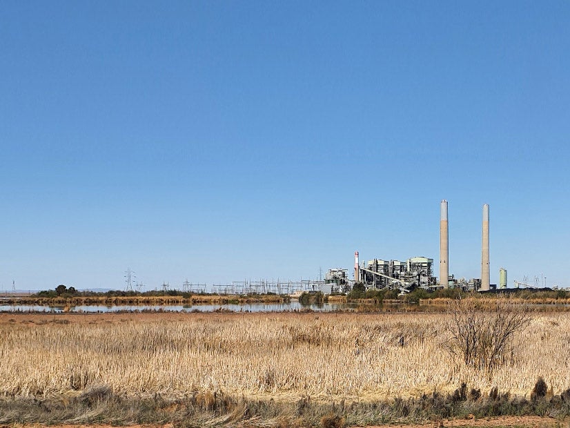
The cover story of this issue reviewed the latest power generation technology then entering the market. "The Fishkill vertical direct acting condensing engine . . . has a heavy bed-plate of box form, with pillow-block for main journal cast on. The upright frames are A-shaped, with hollow cylindrical legs, which rest on the bed-plate and support the cylinder at the top." No details on the height or performance of this machine (Figure 1) were included.
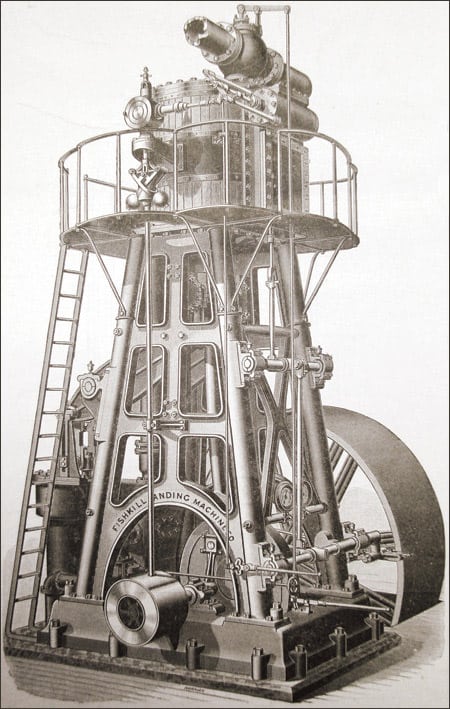
1. A Fishkill vertical direct acting condensing engine, vintage 1885.
One of the key roles of POWER at the time was to serve as a clearinghouse for solutions to practical power house problems. For example, one reader asked for advice on how to measure the power produced by an electric motor, a fairly new need for many power house operators.
The editors responded by suggesting this approach: "Take two maple blocks say 2 in. thick, 2 in. wide, 6 in long; clamp in a vise with strip of card board as a distance piece between their edges; bore a hole, centered in the space between them, equal in diameter to the shaft; fasten the blocks around the shaft by bolts, having fastened a lever to one of them; clamp tight so that the revolution of the shaft shall just keep a weight, hung near the end of the lever, from pulling the lever down. Measure the distance between where the weight is hung and the shaft center and count the shaft turns per minute. Then the power of the motion is equal to the distance in feet from weight support to center, times 6.28, times the weight in pounds. Times the shaft turns per minute, divided by 33.000. Thus if the shaft makes 300 turns a minute and the weight is 10 lbs, 3 feet from the shaft center, the power is 3 x 6.28 • 10 • 300/33,000 = 1.71 net horsepower."
There were also the inevitable letters to the editor, one of which read as follows: "We should much like details of the case in which the engineer reports saving 15 to 20 tons of coal per month by the use of an improved lubricating device. We have for some years been trying to persuade the average lunkhead engine-owner and pig-headed "engineer" (courtesy title, in too many cases of which all know, for "starter and stopper") that there is no economy is first sloshing an engine all over, inside and out, with oil and then letting it run dry and cutting; that it takes more oil, more coal and more repair-bills, (to say nothing of time lost from shut downs) than where a decent lubricating device is used. But it is rarely that even with a goal of coal saving as a test we can prove the fact. ‘Tis a fact all the same."
January 1907
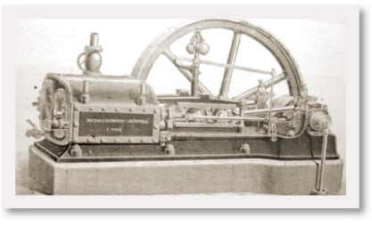
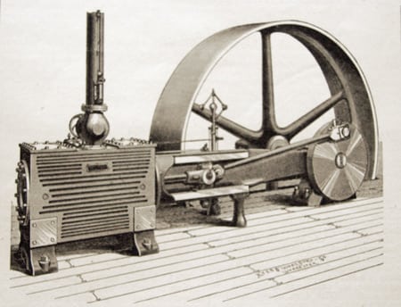
A means for measuring horsepower was a consistent theme early in the 20th century. The editors back then were intrigued by a new gizmo for doing so (Figure 2) that later become known as a dynamometer. "To overcome the difficulties usually attending the measurement of brake horsepower, an ingenious device has been patented by F. Sellers. It consists of a lever, on one end of which is a wooden brake block running on small flanged wheels, and attached to the spring balance B. The lever is placed under the pulley with the block pressing against the rim of the pulley and the fulcrum resting of the floor. . . . This idea is certainly clever, and the device will doubtless become very popular."
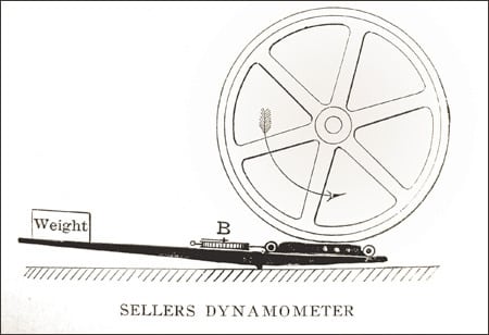
2. The ancestor of the dynamometer, circa 1907.
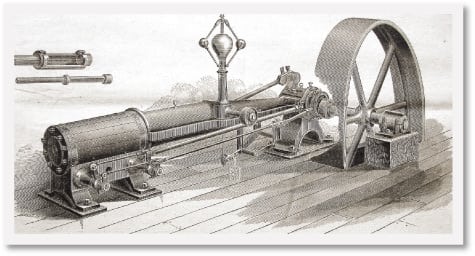
With 20/20 hindsight, today’s editors agree that this is a much more viable approach than bolting two blocks of wood together, as suggested 22 years earlier. In the first decade of the new millennium, there was growing demand for standby power for factories due to the low reliability of central station grids. The automaker Packard certainly made use of the parts at hand. In perhaps the first instance of using automotive engines to produce electricity for plant backup power, an "adaptation of a high-speed automobile gasoline motor to the work of dynamo driving" was reviewed (Figure 3).
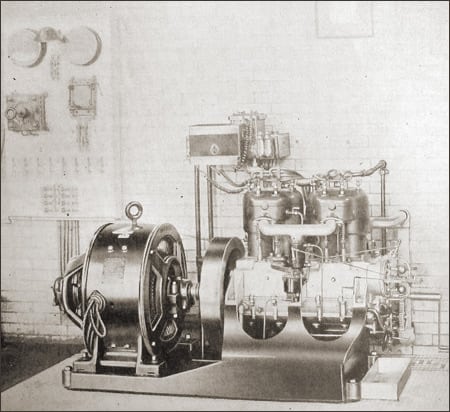
3. An early 20th-century automobile engine driving a dynamo (left) to produce backup power for a factory.
"The dynamo is a 10-kilowatt Westinghouse generator, rated at 40 amperes and 225 volts, and it runs at 800 revolutions per minute. It is used in the factory of the Packard Motor Car Company, of Detroit, Mich., to supply electric light throughout the office and factory at times when the main power plant is not running, as at noon and in the evening. . . . The generator is direct-connected by a rawhide-strap flexible coupling of special design to a Packard marine motor, [a] regular 1906 Packaged automobile motor rated at 24 horsepower."
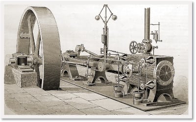
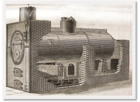
One familiar-looking new product reviewed by the editors was the improved Neemes Grate (Figure 4), manufactured by the Neemes Brothers of Troy, N.Y. "[It is] designed for use in furnaces six feet in length and over, is a combination of the well-known shear-cutting grate of the builders for the forward section, with a shaking and dumping grate for the back section. The front or thin part of the fire can be kept clean without loss of combustible and with the least possible disturbance. The thicker fire at the back can be clinkered from the bottom, or the fire can be raked forward and the clinkers pushed on to the back section and dumped."
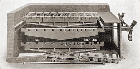
4. A new (in 1907) furnace grate with improved cleaning features.
January 1932
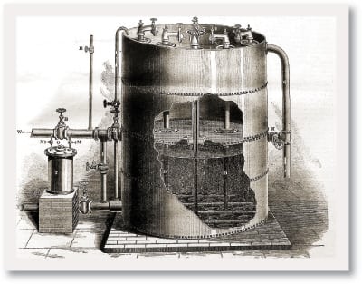
A number of new projects that went into service during 1931 were profiled in the January 1932 issue of POWER. One new "high pressure" installation was the rebuilt section of Pacific Gas & Electric Co.’s Station A that went into service early in February. At this plant, three new high-pressure boilers (Figure 5) replaced 15 old units. "They deliver steam at 1,400-lb pressure and 750 deg. to two 50,000-kw vertical-compound turbines. These units have operated at 62,000 kw and generated a kilowatt for under 12,000 B.t.u. Natural gas is the fuel, and at the present time about 27,000,000 cu.ft. is being used daily in the high-pressure boilers of the station. Steam reheaters have been provided for each turbine, and two of the three boilers are equipped with gas reheaters."
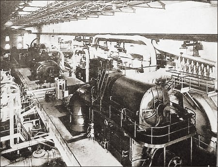
5. Plants craved higher steam temperatures and pressures in 1932, just as they do today. Shown is a section of a Pacific Gas & Electric station that was rebuilt to house boilers operating at 1,400 psi and 750F.
POWER editors noted that "steady progress along conservative lines marked the 1931 program of boiler developments. There is a noticeable trend among the plants going into operation, or laid down during the year, toward higher steam temperatures. The prevailing temperature of 750 deg., with few exceptions in this country, has been boosted in the new plants to 825 deg. The largest boiler installation recorded during the year was that of eight boilers at the Hudson Avenue station of the Brooklyn Edison Company. Each boiler has a steam capacity of 530,000 lb per hour, maximum, at 440 lb and 750 deg total temperature. [Also,] two 1,400 lb.-pressure boilers of 700,000 lb an hour capacity went into operation during the year at the River Rouge plant of the Ford Motor Company. The first boiler installation in the country to operate at 1,800 lb was put into operation during the year by the Philip Carey Company, Lockland, Ohio. Each of the two boilers installed is rated at 150,000 lb of steam an hour with a total temperature of 820 deg. F. They have 40-in forged drums having a thickness of 5 inches."
January 1957
Philadelphia Electric Co.’s announced plan to build the Eddystone Plant got a minor slug on the cover of this issue (Figure 6). The plant, wrote the editors, will be "designed to achieve a net heat rate of 8016 Btu per kwhr, 42.6% thermal efficiency, [with] a projected 325,000-kw for 1960 operation. It will run at 5000-psia 1200-F throttle conditions with two stages of reheat to 1050 F."
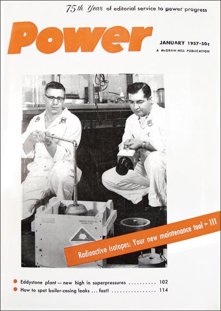
6. The high pressures planned for the Eddystone Plant were noted on the cover of POWER’s January 1957 issue.
In this issue, Steve Elonka—best known as the author of the Marmaduke Surfaceblow series—predicted that plant managers would soon be using Geiger counters as maintenance tools. He provided several potential applications. Radioactive iodine could be "poured into liquids to detect leaks in buried or inaccessible compressed air, water, gas, oil, steam piping." Tracing fluids was described as another possible use, "where the interface between two petroleum products in transit is marked with a small amount of a radioisotope in solution. A [Geiger] counter, mounted at the storage or switch point, instantly shows the end of one product and beginning of next."
Don’t worry, the author did note the "degree of hazard varies greatly with material. Don’t inhale such materials. Isotopes like Cobalt-60 emit powerful gamma rays. Even here, you can easily control hazard by following AEC [the Atomic Energy Commission, the predecessor of the NRC] precautions."
January 1982
POWER reported that the high-temperature gas-cooled reactor (HTGR) at Public Service Co. of Colorado’s Fort St. Vrain nuclear station reached 100% power on November 6, 1981. All systems and components performed at or near design conditions during the test run, according to General Atomic Corp., designer and builder of the 330-MW reactor. "[In the HTGR] helium coolant leaves the reactor core at 1400 F and produces 995 F steam at 2,430 psig to drive the turbine/generator. The plant showed an operating efficiency of 38.5%, higher than any other nuclear power plant and 20% more efficient than U.S. water-cooled units.
"During testing at Fort St. Vrain, operators found that they had up to five hours to recover lost circulation before excessive temperatures developed. Because the helium coolant is chemically inert, it never becomes radioactive. In the full-load test, the circulators that move the heated helium from the core to the heat exchangers surpassed their design flow.
"Fort St. Vrain has been operating under a full-power license from the NRC since 1973. Due to recurring problems . . . in the steam valves, computers, and auxiliary systems . . . the NRC limited the plant to 70% power (200 MW) until the difficulties [are] resolved."