Nuclear power station water storage tanks, located above ground or underground, are constructed of aluminum, stainless steel, or carbon steel. All have naturally occurring electro-chemical processes that can eventually deteriorate the metal, resulting in leaks. Defects that develop on the underside of tank floors are particularly difficult to detect and measure.
The Nuclear Energy Institute (NEI) has recommended that nuclear plant storage tanks, among other infrastructure, undergo periodic inspection. The guidelines for tank inspection were laid out in the publication NEI 09-14 (Rev 1), issued in December 2010. Historically, plant managers have utilized divers or drained the tanks and sent personnel inside to conduct manual surveys and non-destructive examination (NDE) inspections, but that process is often costly, time consuming, and can restrict operation.
An Automated Solution
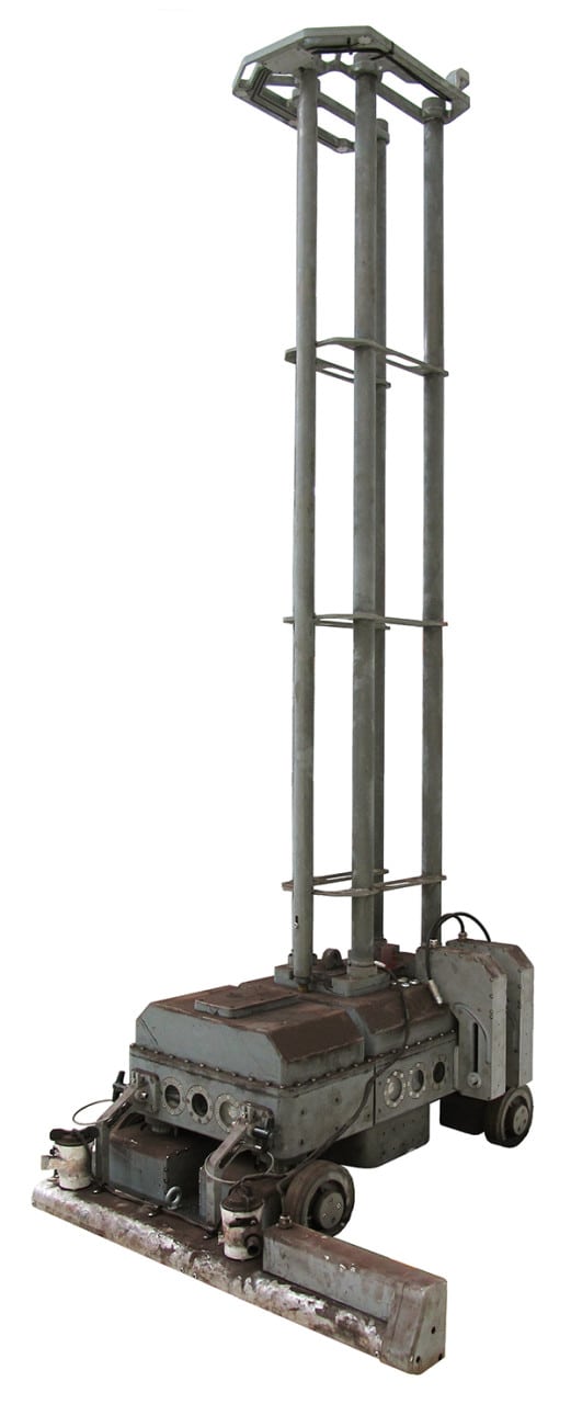
Newton Research Labs and IHI Southwest Technologies Inc. responded to the industry need by developing and implementing automated NDE phased-array ultrasonic and eddy-current array techniques and qualified procedures. The simultaneous acquisition of these data for analysis was accomplished utilizing the Inspector robotic delivery system (Figure 1).
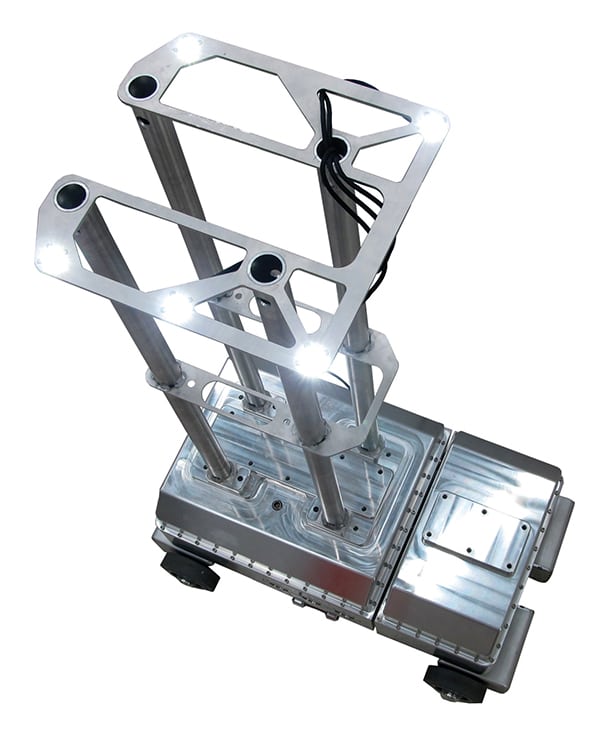 |
| 1. The “Inspector.” This underwater robot can be used to examine water storage tanks as an alternative to draining the tank or using divers. Courtesy: Newton Labs |
The Inspector is a semi-autonomous underwater robotic delivery platform designed to precisely position a variety of sensors, measuring instruments, or repair tools that are used in the evaluation and maintenance of water storage tanks at nuclear power generating stations. There are four major elements to the Inspector system: the robot, the global observation device, the navigation and operation software, and the NDE systems.
The Newton-developed Inspector performs NDE tank floor surveys and inspections without the need for draining or removing the tank from service. It is a unique tool that can position NDE probes and sensors at designated locations in order to perform the NDE inspections on all accessible areas of the tank floor surface. Additionally, data for analysis may be acquired on the wall and near the wall-to-floor interface. The Inspector precisely maps the tank floor, as well as obstacles, and is capable of returning to within one-eighth inch of locations identified for further evaluation.
Versatile and Maneuverable
As a delivery platform, the Inspector is exceptionally maneuverable thanks to an independent, steerable drive wheel system and a split, pivoting chassis design. Wheel pods can rotate 193 degrees, and each wheel drive motor is independently variable. Steering and drive motors are software coordinated, thus giving the Inspector a full range of motion: forward and backward, side-to-side, spin on central axis, diagonal “crabbing,” and radius turns.
Inspector robots are designed to fit through narrow tank entrances or manways (minimum diameter of 19 inches). Lower tank manway entry can also be used if the site can drain the tank just below the bottom entry. The top speed of the Inspector is in excess of six inches per second. The split chassis design allows the Inspector to maintain four-wheel ground contact while moving across surfaces of different elevations.
During deployment, a 72-in-tall mast is attached to the top of the robot. At the peak of the mast are five light-emitting diode (LED) lights, which allow the robot to be tracked by the navigation software. The mast keeps the lights above any sediment or turbidity that may be present in the bottom of a tank.
The robot chassis contains five on-board video cameras, which provide 360-degree, plus down-looking, live video. Additionally, there are laser range finders on all four sides to aid in positioning the unit near the wall of a tank. A built-in down-pointed laser scanner with 0.01-in resolution can measure welds on the floor plates, as well as areas of corrosion. The scanner produces a detailed point cloud output that can be used by a 3-D software program to generate a measurable computer-aided design (CAD) model.
Inspector robots are designed to accommodate several mounting options for NDE equipment, enabling them to map and inspect in very close proximity to the tank wall or internal structures. The sensor mounting options include two indexed arms, mounted to the side of the robot, to which a variety of sensor probes may be attached; an optional, low-slung, arm-mounted equipment plate that may be attached onto the starboard side; and the top deck, which can accommodate additional sensor mounting.
Because storage tanks often have a layer of sediment covering the bottom, the front of the robot chassis has a wide, rotating cylindrical brush assembly attached with two small suction pumps, one on either end of the brush (Figure 2). The brushed sediment is expelled to the sides of the robot by the small pumps.
 |
| 2. It doesn’t do windows, but it probably could. This Inspector robot includes a rotating brush assembly on the front to clean sediment from surfaces prior to testing. Courtesy: Newton Labs |
Getting Down to Business
The robot is lowered into a tank and recovered using steel cables. The robot receives power and communicates with its control console through a power/data umbilical cable. The lifting cable and umbilical are fitted with floats so they don’t impede movement of the robot on the bottom of the tank.
Once the robot is deployed to the tank bottom through the manway, the “god’s-eye” assembly is installed through the manway and clamped to its rim. Input from the god’s-eye camera enables the navigation software to precisely track the robot’s location and position using the bright LED lights on the robot’s mast-top. The god’s-eye assembly consists of a high-resolution monochrome camera mounted at the end of a 24-foot-long boom. Once clamped in place, the boom tip is raised so that the camera is just below the surface of the water and at, or near, the center of the tank.
Inspector robots are capable of operating semi-autonomously or under direct operator control. Search patterns, based upon tank sizes, footprints, and internal floor structures, are pre-programmed into the system. The precise position of an Inspector within a tank is determined using a combination of inputs: the vertical video view from the god’s-eye camera at the top of the tank; the forward, rearward, lateral, and down-looking views from five on-board cameras; and the four laser rangefinders.
Software combines information from these sources with the Inspector’s direction, speed, and position inputs from sensors in the drive motors and wheel pods to create a virtual tank floor environment. The operator can visually track and, when necessary, control the robot with keyboard command in the virtual environment by using the software-generated on-screen robot avatar. In addition to the virtual display, the user interface numerically displays the precise XY-axis location of the robot. The virtual robot displays the path it has traveled with a blue line.
Locations of indications can be pinpointed to within one-eighth of an inch. The coordinates correlate to the plate weld map and are saved within the system. Once the system associates the tank floor weld pattern with the stored weld map, the robot can return to the point of the defects, even if the robot is removed from the tank and redeployed at a later date.
Inspection Techniques
The Inspector’s robotic arms and probe holders deliver IHI’s qualified probes at a specified position for acquisition and analysis using state-of-the-art technology and software. The Inspector is equipped to deploy a phased-array ultrasonic transducer (PAUT) and an eddy-current array probe. The approach used for the tank inspections minimizes the time required for data collection and analysis and maximizes the quality of acquisition.
As part of the data analysis process, 3-D models of system components can be integrated into the system to aid with data analysis interpretation and with indication and corrosion evaluations. Well-qualified and experienced data analysts evaluate the correlation of the indication or corrosion with respect to the inside or outside examination surface proximity. Feedback is provided to the customer in a detailed report with flaw images, dimensions, and locations. The use of 3-D visualization during data analysis provides efficient and auditable data analysis protocols of complex components.
Any potential flaws that may be open to the surface, or opposite surface flaws that are approximately 50% through, can all be verified using eddy-current testing (ECT). An ECT array sensor located adjacent to the PAUT probe complements the PAUT data by providing additional information regarding any surface, and some opposite surface, indications. IHI uses a semi-flexible, multi-coil, driver pick-up mode ECT probe.
Using the latest technology, IHI is able to perform real-time processing, greatly increasing the quality of inspections (Figure 3). Analysts can review the data as it is being obtained, streamlining the process and significantly increasing productivity.
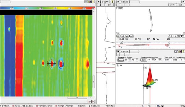 |
| 3. Painting the picture. Strip charts, 2-D, and 3-D graphics allow experienced analysts to easily identify flaws. Courtesy: IHI Southwest Technologies Inc. |
Once deployed on the tank bottom, the robot begins its inspection sequence by locating the tank wall and moving around the perimeter. During this phase, the robot detects and maps where the cross-tank floor plate welds meet the wall. Upon completing the perimeter sweep, the robot follows each long welded joint and detects the short, intersecting welds. This enables the system software to map the location of the individual floor plates as well as any obstructions, such as piping or structural supports.
After identifying all floor plates, the robot is directed to scan the area of individual plates with the attached sensor package, using a “lawn-mowing” pattern to ensure complete coverage. The robot is able to sense obstacles in its intended path and stop before the sensors are damaged. If necessary, the operator can use the on-board 360-degree video imaging system and take manual control to position the Inspector.
Putting Theory into Practice
The Palo Verde Nuclear Generating Station is the largest power facility in the U.S. Located about 55 miles west of Phoenix, Ariz., its three units have a generating capacity of over 4,000 MW. The plant is owned by a consortium of seven utilities and operated by Arizona Public Service (APS).
During Palo Verde’s fall 2014 outage, an examination of an in-service condensate storage tank was required. Roger Fongemie, department leader for APS, explained that although other inspection options were considered, due to the short window of opportunity to complete the examination, the Inspector-series underwater robot was the only method capable of meeting schedule constraints.
As a first-time evolution, multiple planning meetings and mockups were conducted to ensure potential problems were identified. During the outage, IHI engineers conducted the inspection of the tank floor utilizing a combination of phased-array ultrasound, eddy current, laser scanning, and high-resolution cameras all mounted on the Inspector.
The robot was used to survey over 90% of the tank bottom by inspecting each of the 36 floor plates of the 54-ft-diameter tank, as well as visually examining the welds of each floor plate, including where the 52-ft tank wall meets the floor. In the end, the Inspector robotic system successfully gathered all of the data needed to satisfy NEI 09-14 requirements. ■
—Edited by Aaron Larson, a POWER associate editor.