In today’s electricity generating environment, new demands are being placed on fossil-fueled boilers, including operating in cycling modes for which the boilers were not originally designed. In a growing number of cases, these changes are resulting in boiler tube failures. To avoid such failures, regular inspections with the latest examination tools are becoming increasingly critical for identifying areas of damage that can be repaired before they lead to an unscheduled outage.
The most common failure mechanism is corrosion fatigue, a cracking mechanism in fossil-fueled generating plants that stems from a combination of thermal cycling and water chemistry at high-stress areas. One of the largest contributors to forced plant outages, corrosion fatigue predominately occurs in the waterwalls and economizers of subcritical plants. Cracking attributed to corrosion fatigue has occurred in waterwall tubing of both membrane and tangential designs.
Cracking (particularly in membrane waterwall tubing) presents a challenge for conventional nondestructive evaluation (NDE) because the condition manifests itself as multiple cracks that initiate and grow on the inside surface of the tubes and on the insulated side of the tube—locations not usually accessible due to the presence of insulation, building structural components, and exterior building covering.
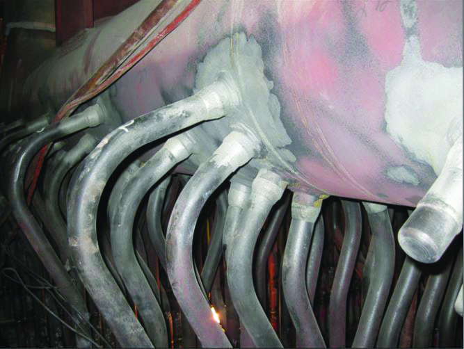
A typical location that may experience corrosion fatigue is shown in Figure 1. Notice the presence of the scallop bar and casing structure, which limits the use of conventional NDE, either ultrasonic or radiographic. The outer building structure (not shown in Figure 1) is farther from the waterwall tubes.
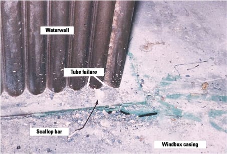
1. Tough spot. Here is one location where corrosion fatigue failures can occur on boiler waterwall tubes. Courtesy: EPRI
Nondestructive evaluation techniques
Today the most common types of volumetric examination techniques in power plant environments are ultrasonic and radiographic.
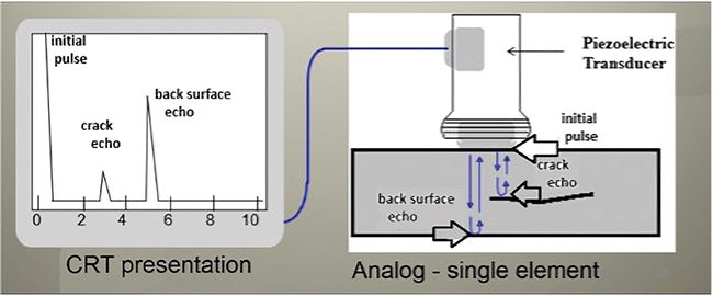
Ultrasonic examination involves the introduction of high-frequency sound waves into a component for the purpose of determining some characteristic of the material, such as flaws or thickness. However, to date, ultrasonic examination has not been successfully applied to detect corrosion fatigue cracking from the fireside of boiler waterwall tubes, though progress is being made by EPRI with the use of ultrasonic phased array probes.
Conventional film radiography has long been a primary weld examination technique and has been accepted as a valid means of crack detection for many years. This technique passes radiation through the component and records the exiting backside radiation by either photographic or electronic means. The radiation may be produced either by a radioactive source (gamma) or by an x-ray machine.
The advantages of film radiography are that it provides a permanent film record of each examination for archiving and later review, and it is the ASME Code–approved method for examining numerous types of welds. Its disadvantages are these:
- It requires significant safety requirements (the test procedure must protect personnel from radiation exposure, and radioactive sources must be handled properly by qualified personnel).
- It is nonquantitative (flaws cannot be located or sized precisely).
- Results for components with complicated, nonuniform section thickness can be difficult to interpret.
- This technique cannot offer quick results because the film needs to be placed, removed, and processed.
In addition, conventional film radiography has limitations specifically with corrosion fatigue cracking because of the loss of sensitivity when passing the radiation beam through heavy components on the outside of the boiler.
Direct-digital radiographic systems
Radiographic techniques have undergone a number of technological advances in recent years. Ten years ago, the advent of phosphor plates eliminated the need for film in radiographic systems, removing the need for chemicals used during the development process and allowing for digital storage of the images of examined components. In 1997 an EPRI study showed that the phosphor plate equipment available at the time was effective for a range of utility power plant applications and could be utilized as an examination technique while further refinements were under way.
In the late 1990s direct-digital radiographic detectors were developed. Initially, the resolution of these detectors was inadequate for detecting cracking, and the emphasis of their use was on wall thinning. In 1998, EPRI collaborated with the petrochemical industry to assemble a direct-digital detector radiographic system for the detection of wall thinning in pipe. More recently, improvements in technology have evolved to the point where digital detectors have become smaller, and their resolution has improved sufficiently to make them suitable for the identification and analysis of corrosion fatigue cracking.
Direct-digital radiographic systems offer a number of advantages for NDE, including:
- The potential for real-time or near-real-time examination because film does not have to be developed.
- The ability to move the detector to obtain better understanding of component geometry and flaw orientation.
- Scanning of a component to allow compilation of three-dimensional tomographic images for defect characterization and sizing.
In addition, with digital detectors providing up to 10 times the sensitivity of radiographic film and the ability to align the radiation beam, personnel exclusion zones are being reduced to an area of only 10 to 20 feet rather than large areas that could include entire buildings. Also, direct-digital radiographic systems may offer the potential to estimate crack depth by monitoring the radiographic density profile.
EPRI’s prototype system
EPRI is developing a direct-digital detector using photosensitive complementary metal oxide semiconductor (CMOS) technology. The system is based on an advanced digital detector and other proprietary hardware and software from Envision Product Design.
The system includes:
- X-ray radiation source (300 kV, 10 mA). Detector (18-inch-long segmented CMOS array with spatial resolution of 0.003 inch).
- Motion-control system with image-capture software for acquiring, enhancing, and managing the resulting x-ray images.
- Remotely operated robotic device for positioning the detector and the x-ray device throughout the boiler.
Integrated software controls the alignment, calibration, and movement of the detector and the image data acquisition. This software helps to keep the x-ray beam and detector aligned by speeding up or slowing down motion when the two devices start to become misaligned. The detector moves along the waterwall inside the boiler, carried by a robotic scanner, while tracking the source or x-ray tube, which is mounted on its own scanner inside the boiler. The software keeps the two in alignment by monitoring the x-ray intensity.
Qualifying direct-digital radiographic systems
To implement direct-digital radiographic technology and take advantage of its possible benefits, the overall system capability must be appropriate for the component and type of defect one is trying to detect. For power plant applications, the technology’s capability and limitations should also be demonstrated so that false assumptions on probability of detection do not occur.
Many different types of direct-digital detectors exist, but in order to be accepted for use in the power industry (and most others), the detectors’ capability must be well-understood. Quantifying the capability of film radiography took decades, even though there were significantly fewer variables with film than there are with digital detectors.
Although there were different film manufacturers and differences between films, film types were relatively standardized and classified such that comparisons could readily be made. Digital detectors, on the other hand, can be significantly different from one another. Also, with the addition of electronics in both image capture and image display, the number of variables is much greater than in a film radiographic process.
As a result, evaluating the performance of various systems on a single application (component) could take considerable time. Conversely, to develop an understanding of performance of even a single system so that its capability could be predicted on a variety of components would also require significant effort. The task becomes even more complex when using each type of detector in combination with many different radiographic sources.
Because the performance of digital detectors is quite different from that of conventional radiographic film (greater sensitivity and increased dynamic range, for example), it is difficult to rely on past experiences in order to draw comparisons about digital radiographic performance on a given component. Even if such comparisons could be defined, there is very little experimental information available on the performance of film radiography. Further complicating the issue, the requirements of the ASME code themselves are based on experience and expert opinion that has been collected over many decades and is not well-documented.
Field testing
A field trial of EPRI’s prototype system was performed at American Electric Power’s (AEP’s) Conesville Unit 1 boiler during the week of April 21, 2008. Conesville Unit 1, a 125-MW coal-fired unit in Ohio, has been permanently retired and hence presented an excellent venue for testing this technology. The first test consisted of verifying the performance on a 12-foot horizontal track; a second field test will extend the range of motion to include vertical travel and tilt of the detector.
Field testing determines how to best locate the source outside the boiler and coordinate both detector and source. It also involves quantifying the system’s crack detection and sizing capabilities and investigating other digital radiographic boiler examination possibilities, including the detection of flow-accelerated corrosion through insulation.
Laboratory test results indicate that the digital radiographic system can provide the same results as conventional film radiography. Figure 2 provides a comparison of digital radiographic results and digitized film radiography on the same set of waterwall tubes. As can be seen in Figure 2, the digital radiography is at least as sensitive as optimized conventional film radiography.

2. Comparing cracks. Compare an x-ray digital detector image (top) with the digitized x-ray (bottom) of the same crack. Courtesy: EPRI
The Conesville field trial showed that the prototype system could be deployed by mounting the digital detector on a section of horizontal track attached to scaffolding inside the boiler with the x-ray tube mounted on a second section of horizontal track mounted to scaffolding outside the boiler. The motion control system, with image capture software, then properly aligned the detector and source and maintained correct alignment throughout the scanning. This setup is shown in Figure 3. In the field trial at Conesville, the x-ray tube was placed approximately 40 inches from the boiler tube in order to allow maximum scanner travel around various obstacles outside the boiler. Personnel were operating the data acquisition equipment just around the corner of the boiler, approximately 20 feet away—a significant reduction in distance from the conventional radiological exclusion zone for personnel.

3. A new track. The x-ray tube was mounted on track outside of the boiler; various obstacles stood between the x-ray tube and boiler tubes. Courtesy: EPRI
While scanning at a rate of approximately 1 foot per minute, radiographic images were acquired of boiler tubes through both walls of the tubes, refractory, buckstays, boiler casing, insulation, and the external skin of the boiler. Some of the boiler’s exterior had previously been removed because of corrosion fatigue cracking. Figure 4 shows the configuration as viewed from the exterior of the Conesville Unit 1 boiler. Images of cracked tubes and thinned tubes were acquired. Figure 5 shows corrosion fatigue cracking in a boiler tube after exposure to 300-kV x-rays.

4. Boiler layers. The x-rays needed to penetrate several layers. Courtesy: EPRI
5. Screening for cracking. This digitized radiographic image of boiler tubes shows corrosion fatigue cracking. Courtesy: EPRI
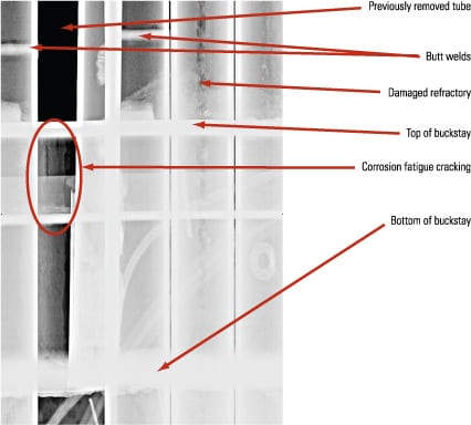
Figure 6 shows the digitized radiographic image along approximately 70 inches of waterwall, including 26 tubes. In this figure, the second tube from the left had been previously removed. Above the buckstay, in the place of the removed tube, a different tube containing corrosion fatigue cracking was inserted. This tube is angled somewhat, and the corrosion fatigue cracking is clearly visible. Note also that several circumferential welds can be seen in the radiographic image where earlier tube replacements occurred.

6. No longer invisible. A digitized radiographic image of wall panel revealed corrosion fatigue cracking. Courtesy: EPRI
Once performance trials have been completed, the system will progress to final development and commercialization. EPRI will be looking for NDE vendors to utilize this technology while supplying examination services.
Crack depth sizing possibilities
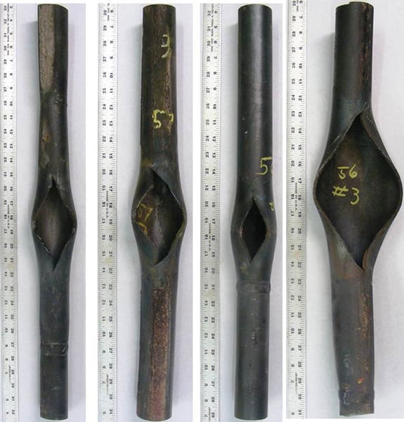
While preparing the digital radiography system, it was noted that some cracks are quite straight and that using digital radiography could result in potentially estimating crack depth by monitoring the radiographic density profile. Thermal fatigue cracks that occur as a series of multiple circumferential cracks on the outer surface of boiler waterwall tubes seemed to have a geometrical shape (straight and V-shaped) that would permit depth sizing by this method. Figure 7 shows the outside surface of a boiler tube with thermal fatigue cracking. The image above the cracked surface is the digital radiographic image of the same cracked sample, with the crack depths as determined by destructive analysis shown on the radiograph.

7. Crack attack. Outer-diameter cracked surface with radiographic examination image and actual crack depths. Courtesy: EPRI
To verify the hypothesis, a calibration tube was manufactured with known-depth flaws. Then a section of boiler tubing containing thermal fatigue cracking was exposed and the digital image was analyzed. The density profile was imported into a spreadsheet, where an algorithm was written to compensate for density variations along the tube length. The radiograph shown in Figure 7 is again presented in Figure 8, this time with the resulting graph of the density profile along the center of the cracked tube. The density profile in Figure 8 is shown in simple gray-scale values. After converting the gray-scale values to depth via the spreadsheet, crack depth estimations were reported with an accuracy of 5% of the tube wall thickness.

8. Finding hidden cracks. Density profile of cracks and actual depths. Courtesy: EPRI
Although this was a single test of using the density profile to estimate crack depth, it does appear as though this technique will be promising for the types of cracks that are very straight—such as those produced by thermal fatigue. At least it will provide a means of ranking a series of cracks and identifying the likely worst-case, deepest crack.
—Stan Walker (swalker@epri.com) manages EPRI’s Fossil NDE activities. He has 35 years of power-industry nondestructive evaluation experience and has been with EPRI in Charlotte, N.C., for the past 25 years.