An increasing number of low-pressure steam turbines—especially at supercritical fossil units—have experienced stress corrosion cracking in the blade attachment region of their low-pressure rotors. Approaches to solving this problem range from redesign of the attachment and blade replacement to in-situ weld repair. Regardless of the procedure selected, the solution must completely restore the turbine performance while minimizing outage duration.
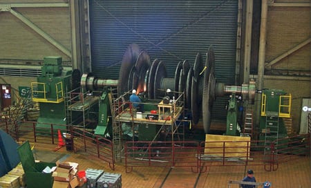
Tennessee Valley Authority’s (TVA’s) Paradise Fossil Plant, located in western Kentucky, consists of three units that began commercial operation between 1963 and 1970 that have a total generating capacity of 2,273 MW (Figure 1). In 2007, there was trouble in Paradise at Unit 3.

1. Many cracks found. Unit 3 at Tennessee Valley Authority’s Paradise Fossil Plant uses a supercritical steam generator operating at 3,500 psig. The steam turbine is configured as a cross-compound four-flow with 52-inch last-stage blades (CC4F52). Rotor repairs were recently completed on both low-pressure steam turbines to correct cracks found in blades and rotors caused by stress corrosion cracking. Courtesy: TVA
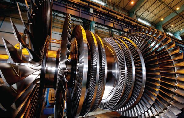
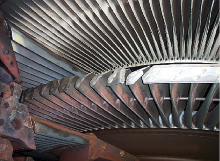
Unit 3 is equipped with a Babcock & Wilcox supercritical steam generator operating at 3,500 psig with 1,000F main and reheat. The 1,150-MW steam turbine is a General Electric cross-compound design whose high-pressure (HP) and first reheat (IP1) turbine section are coupled to a 3,600-rpm generator. The double-flow IP (IP2) and the two low-pressure (LP) turbines are connected to a second generator, rotating at 1,800 rpm. Each LP turbine has a double-flow configuration with 52-inch last-stage blades (Figure 2).
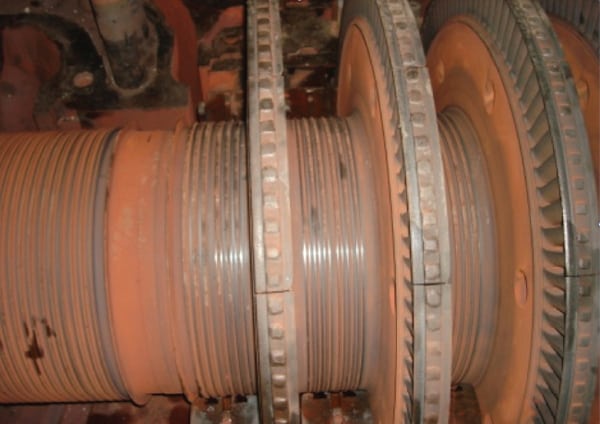
2. Double rotor inspection. The low-pressure turbine is configured with two, double-expansion turbines. This is the Unit 3 LP-B rotor chucked up in a lathe for machining. It weighs 308,275 pounds and is 17 feet from tip to tip of the largest blades. Courtesy: TVA
TVA’s standard steam turbine inspection interval is approximately 10 years. The spring 2007 maintenance outage at Unit 3 included a standard nondestructive examination (NDE) rotor inspection with phased array ultrasonic test (UT) inspections of the L-2 and L-3 blade wheel attachments in the LP turbines. Test results showed multiple indicators of what was believed to be stress corrosion cracking (SCC) on both LP rotors. The indicators were confined to the L-2 and L-3 stages of each LP rotor, although the extent and severity of cracking in the dovetail attachments was different between the stages.
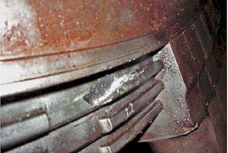
There are 127 blades plus 1 locking (notch) blade in the L-3 row. Also, the L-2 stage on the LP-B rotor shroud covers on a section of the stage appeared to have moved outward and contacted the stationary diaphragm (Figure 3). The shroud failures and disk root indications strongly suggested that an early, extended repair outage was necessary.
3. Shroud of turbine. The inspection also found that the LP-B rotor L-2 stage shrouds had failed. Courtesy: TVA
The problems experienced by Paradise Unit 3 may be expensive and time-consuming to repair, but they are not unusual. To assist others facing similar problems, this article reviews the repair options for each stage identified by the TVA, the decision criteria used, and the solutions selected.
L-3 stage repair
The vulnerability of the L-3 stage dovetails to SCC during normal operation is limited because minimal wetness is present at this location. The steam dry-to-wet phase transition zone in an LP turbine is typically the location of the worst SCC. In the case of Unit 3, SCC was identified in both LP turbine rotors. Severe cracking in the dovetail of a typical fossil LP turbine is illustrated in Figure 4.
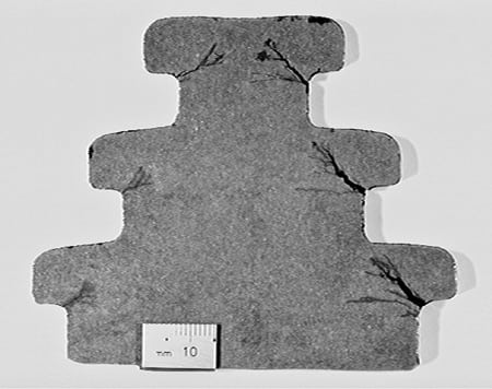
4. Imminent failure. A typical low-pressure steam turbine blade dovetail damaged by stress corrosion cracking, which can cause extensive damage if the condition is not quickly corrected. Courtesy: TurboCare Inc.
For the LP-B rotor’s L-3 stage, TVA elected to remove the notch blades to confirm the UT inspection results as well as the location and extent of the indications. A magnetic particle test (MT) was used to confirm the indication depth and length. Only two of the eight indications reported by the UT were confirmed with MT, but another five indications were found by MT that had been overlooked by UT.
From a remaining life standpoint, the worst combination of indications were aligned circumferentially at the stage 2T upper and middle hooks near the notch entry after excavation (Figure 5).

5. Many indications found. LP-B rotor critical indications numbers 8 and 10 on the L-3 stage discharge side middle and upper hooks are shown after completing excavation. The indications were caused by stress corrosion cracking. Courtesy: TurboCare Inc.
Additional UT tests of the L-3 stage LP-A rotor were performed in April 2007. The most significant indications were reported in lower dovetail hooks of the L-3 stages. The worst indication was measured by MT after excavation as having a maximum depth of 0.56 inch and a length of 2.5 inches (Figure 6).
6. More problem indicators. LP-A rotor critical indication number 8 is illustrated on the L-3 discharge side lower hook. An excavation of 0.5625 inch x 2.5 inch was ground out for the repair. Courtesy: TurboCare Inc.
Evaluating the options. For the two rotors, both short-term and long-term mitigation strategies for dovetail SCC were considered. The good news was that the cracks found on each wheel were confined to the entrance notch area. Sorting through all the available short-term repair options produced a short list of strategies that would minimize the length of a repair outage:
- Do nothing.
- Reduce loading at crack locations adjacent to the notch by pinning the notch blade directly to the wheel
- Reduce blade load by using titanium blades, which are 43% lighter than steel, although replacing steel blades with titanium blades creates a mass imbalance on the rotor.
To determine which option to choose, TVA’s detailed analysis began with collecting the dovetail profile dimensional data and constructing a finite element model (FEM) of the L-3 dovetail. A plot of the rotor dovetail region of the FEM is shown in Figure 7, as are the calculated stresses normal to typical dovetail crack trajectories. These stress distributions are normal to the plane of cracking away from the notch entry, at rated speed (1,800 rpm). The blade root (dovetail) FEM section (Figure 7) was also included in the FEM with gap (contact) elements simulating load transfer from the blade to the disk at the top, middle, and bottom loading lands.
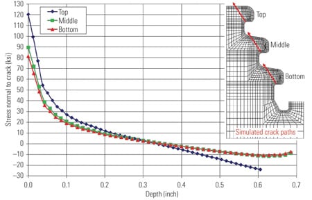
7. Stressed blades. A finite element model of the LP-A L-3 dovetail determined the level of stress found normal to the cracks and included load transfer from the blade to the disk on the three lands. Source: TurboCare Inc.
The stresses do not include the load increase at the notch entry. This is accounted for in LPRimLife software using a load scale factor. LPRimLife is a program that evaluates the remaining life of rotors with known or suspected blade-attachment cracking. Its development by Structural Integrity Associates was sponsored by the Electric Power Research Institute.
The first step in the evaluation was to estimate the stage operating temperature and wetness. Wetness is a prerequisite, as SCC is not expected for attachments that encounter superheated steam during steady-state operation but during transient start-up and shutdown conditions. However, wetness during operation, when the dovetail attachments are fully loaded, makes the attachments susceptible to SCC.
Three loading options at the notch were evaluated over the expected operating load range, at overspeed up to 110%, with two different rotor start-up temperature profiles, and the like, as required by the rotor fracture mechanics software code. The code also accounted for the crack depth and length in the upper, middle, and lower hooks and was based on the NDE and/or grindout confirmation values. A crack depth uncertainty of ±0.060 inch and length uncertainty of ±1.0 inch were simulated.
Also, unlike the dry-to-wet transition predicted to be just upstream of the L-2 stage, and confirmed with the extensive SCC discovered in the L-2 stage dovetails, the L-3 stage is not expected to run “wet” during normal operation. The less severe cracking in the L-3 stage dovetails, which was confined to the entrance notch area, is consistent with this prediction. To account for transient wetness, 1,750 hours per year of wet time were conservatively simulated in the L-3 dovetail evaluation.
Evaluating simulation results. The probabilistic simulation results from LPRimLife estimated the “cumulative probability of failure” versus operating time in years for each of the three repair options:
- The “do nothing” option returned very high failure probabilities for the notch after another year of operation.
- The option of pinning the blade to the wheel as an interim fix significantly reduced the failure probability to below 1% for five more years of operation.
- The option of replacing the banded group of blades at the entrance notch with titanium blades resulted in a prediction of 10 more years of operation with a failure probability below 0.01%, or 20 more years with a failure probability below 0.65% (Figure 8).
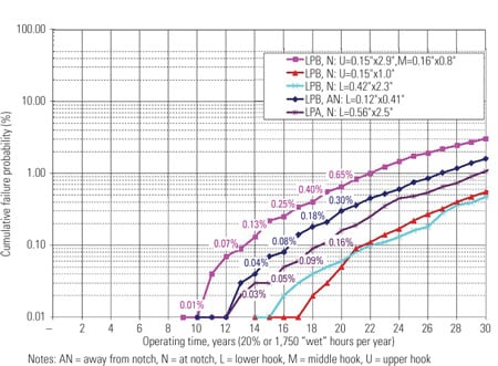
8. Option 3 selected. The choice of repair strategy for LP-A rotor stage L-3 (stage 6) dovetails was determined by a detailed probabilistic analysis by Structured Integrity Associates using the LPRimLife life assessment computer program it developed for EPRI. The analysis results showed that using titanium blades with notch blades pinned to the wheel, with three pins in the axial to the wheel and four cross-pins, was predicted to deliver 10 more years of operation with a failure probability below 0.01%, or 20 more years with a failure probability below 0.65%. Source: TurboCare Inc.
TVA selected the third option as the most effective interim repair for mitigating the risk of dovetail failure at the notch.
Rebalancing. To minimize repair cost and reduce repair time, TVA did not want to disturb the remaining blades on the wheel. But it knew that the difference in material density between the existing and the new, lighter-weight blades would create a significant mass imbalance on the disk that would adversely affect rotor vibration. The entrance slots to the two L-3 stages are oriented 180 degrees out of phase with respect to each other. This creates a dynamic couple imbalance on the rotor that requires a significant weight correction.
To address this concern an analysis was completed that determined the potential imbalance on the rotor and the expected change in rotor vibration. Because both L-3 stages on each rotor would be modified with the titanium blades, the total imbalance would be double that for one disk. The correction capacity for the existing balance planes on the L-1 and L-4 stages was insufficient to correct for the expected imbalance. The L-0 stages were not considered for the correction but were reserved for trim balancing in operation.
To correct for the imbalance, two vanes were removed from each disk at approximately the five and seven o’clock positions to counterbalance the mass reduction at the titanium blades. The removal of the blades required the shroud band groupings to be evaluated to ensure that there was not a significant change to blade natural frequencies. The LP-A rotor also presented the complication of a lacing (tie) wire in both disks that required adjustment with the removal of the two vanes.
Removal of the two vanes did not precisely balance out the titanium group, so each rotor was low-speed balanced prior to reassembly to minimize residual imbalance. Acceptable rotor vibration on both rotors was achieved running up through the critical speeds and at operation speed. No trim balance corrections were needed on either rotor.
The design, machining, and assembly of replacement blades for the L-2 stages were completed concurrently with repairs on the L-2 stages, discussed in the next section.
L-2 stage repair
Ultrasonic testing results for the LP-B rotor found many more indications than on the L-3 rows just discussed. Ninety-eight indications were dispersed on all the hooks and were distributed around the entire wheel with a depth ranging from 0.04 inch to 0.39 inch on the generator end. The LP-A rotor (turbine end) was found to be in a similar state, with 78 indications ranging in depth from 0.04 inch to 0.26 inch on all three hook fillets and on both sides of the wheel.
Bigger problems/bigger solutions. TVA expressed a strong desire to maintain its original outage schedule on the turbines and to minimize any reduction in power generation after the repairs were completed. TurboCare, in conjunction with Structural Integrity, investigated several repair options to achieve TVA’s goals. Collectively, the team determined the best solution was a longshank replacement design. However, the longshank repair would also require the longest repair time in an already compressed upcoming planned outage.
The L-2 stage was much more susceptible than the L-3 stage to SCC because of higher stresses in the root and higher moisture content in the steam. The L-2 disks had more extensive disk dovetail cracks, requiring a complete redesign of the blade, modification of the wheel rim, and the use of titanium at the notch area to reduce blade attachment stresses. The redesign also included L-2 blade frequency testing and optimum frequency tuning of blades with over/under shroud covers for vibration control.
Repair of the L-2 stage involved machining the wheel root form in undamaged material. The general approach has been to first remove all blades and then to grind out the deepest indications to determine the crack depth. The minimum distance required to reestablish the root form is determined by overlaying the excavations and the root form. This approach could have lengthened the outage.
Because of TurboCare’s experience with many other longshank blade projects, the amount of drop—and therefore the amount of material removal required to ensure all the cracks were removed—was engineered and implemented with minimal delay. Concurrently, the design and manufacture of the replacement blades was started before the original blades were removed from the existing wheel.
The longshank redesign process also allowed the attachment form to be improved from stock conditions. The dovetail was machined with modified fillet radii to reduce the peak stresses for two reasons: to offset the additional weight from the longshank modification and to reduce the stress concentration factor of the geometry, which contributes to SCC (Figure 9). The reduction in peak stress is typically 10% to 15% for this modification.
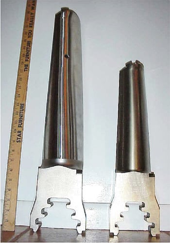
9. Add longer blades. The blade on the left side is nearly identical to the L-2 longshank design used on this project. To accommodate the longer blade, the rotor must be machined to a reduced diameter and a new dovetail added. Courtesy: TurboCare Inc.
Frequency and vibration management. An important element in this process was designing a replacement blade with natural frequencies away from the operating speed. The tuning of frequencies was required to compensate for the change in the root attachment location. Generally in the design process, several parameters are investigated to optimize frequencies such as vane scaling, shroud configuration, shank length, and blade count.
Despite the short lead time to engineer a repair, all design calculations were expedited to minimize any outage delays.
Another important feature of the design is the use of chain link or over/under shroud covers. This design replaces the original single shroud segment with a two-tiered shroud. The inner shroud is assembled with a clearance around the tenon, and the outer segment is rigidly connected to the upper section of the tenon (Figure 10). The inner and outer segments are circumferentially offset to provide a continuous coupling of the blade tips. This configuration provides a significant increase in vibration damping and also suppression of several fundamental vibration modes caused by steam path excitation. This design provides an additional vibration safety margin with the ability to supplement tuning of blade frequencies to avoid the impulse line (1X running speed) with both the five and six nodal diameters.
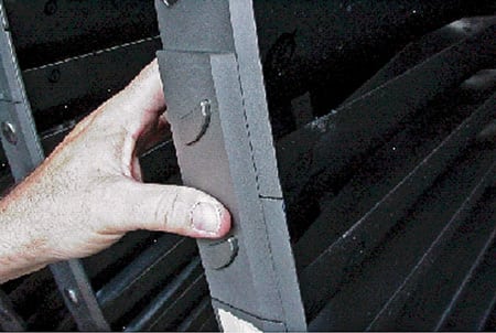
10. Lapped joints. A typical over/under shroud assembly was added to L-2 to continuously couple the blade tips. This design approach increases blade vibration damping. Courtesy: TurboCare Inc.
To decrease the likelihood of SCC reoccurring in the repair, the design included five titanium blades at the entrance notch. Experience has shown that SCC usually occurs at this location first because of the locking closure piece arrangement. Titanium reduces the centrifugal load of the blades on the wheel in this area because of the 43% reduction in material density. To minimize the potential mass imbalance on the rotor for the titanium blades at the notch, five titanium blades are assembled 180 degrees opposite the entrance notch group.
The complete treatment plan. The final design required removal of all the SCC-damaged material and replacement with a set of blades tuned away from resonance frequencies, superior damping for vibration control, and improved geometry to reduce the reoccurrence of SCC.
These repairs were supplemented with a low-speed rotor balance at the site for a smooth turbine restart.
—Bruce Gans (bgans@turbocare.com) is chief technical officer for TurboCare Inc. Darryl A. Rosario, PE (drosario@structint.com) is an associate with Structural Integrity Associates Inc. Jim Olson (jrolson@tva.gov) is a principal engineer and Jerry Best (hgbest@tva.gov) is manager of the steam cycle and generator systems department for Tennessee Valley Authority.