The regenerative feedwater cycle of modern fossil and nuclear power plants normally includes four or five low-pressure, closed (tube surface-type) feedwater heaters (CFWHs). However, maximum efficiency can be obtained when CFWHs in the power plant cycle are replaced by direct contact heaters (DCHs). Advancements in steam injector technology, such as Fisonic devices, have helped make DCHs an attractive option.
Although only a small portion of a plant’s total cost, regenerative feedwater heaters have a significant influence on the economy and reliability of power facilities. Equipped as they often are with costly large tube bundles, it is well appreciated that the low-pressure closed-type feedwater heaters (CFWHs) can be a potential source of harmful impurities in the feed cycle.
Typically, the first CFWH after the power plant condenser operates under a vacuum. Field tests have shown that the actual value of the outlet terminal temperature difference (TTD) in this type of heater regularly exceeds the design figure. This is caused by the fact that the design TTD is determined by assuming that practically no steam pressure drop occurs across the tubing bundle. In fact, the steam pressure drop in the tube bundle can be as high as 2 psi, which means about a 10F decrease of the saturation temperature in the vacuum.
The second thing that causes an increase in the outlet TTD is the presence of air in the steam. Air leaks into the system through poor seals in piping and related systems. Air can also leak in with the steam from the turbine gland steam system when its normal operating condition is disturbed. The TTD increases rapidly if the amount of air in the steam is higher than 0.05%.
The increase in the TTD in CFWHs operating under vacuum results in a decrease in the extraction steam flow from the last stages of the turbine, and it increases the steam flow from the higher-pressure stages to the heaters. This in turn reduces the thermal efficiency of the unit. The increased outlet TTD of the condensate in the vacuum CFWH also leads to thermal overload of the following CFWHs, which in turn increases the steam velocity and causes vibration of the tubing system. This has been identified as one of the main reasons for tube failures.
Operating experience and field tests have shown that with turbine load less than 50% and under transient conditions, unless special provision for deaeration in the condenser at low load is made, an increase in the oxygen concentration in the condensate will result. If a vacuum in the condensate polishing system (CPS) occurs, it also leads to enrichment of the condensate with oxygen and carbon dioxide.
Failure of tubes requires a heater to be taken out of service immediately because of the potential hazard of water induction into the turbine. This of course reduces the overall cycle efficiency. In addition, low-pressure CFWHs have several inherent disadvantages, which are difficult to avoid even with careful design, manufacturing, and maintenance. They include:
- ■ Poor venting of the steam space of CFWHs during startup, shutdown, and transient conditions leads to an increase in the concentration of non-condensable gases, which in turn causes corrosion of tubes and internal surfaces of heater shells.
- ■ Field tests have shown that tubing in low-pressure CFWHs is one of the main sources of impurities in power plants, which can cause erosion and corrosion.
- ■ CFWHs require rigid quality control in the fabrication of tubes and during installation.
- ■ Environmental conditions must be carefully controlled during shipping, storage, erection, testing, startup, and operation.
It is common practice in power plant design to use 5F as the TTD for the condensing section of a CFWH and 10F as the approach in the drain cooling section. Maximum heater efficiency can be obtained when CFWHs in the power plant cycle are replaced by direct contact heaters (DCHs) with zero temperature difference. With DCHs, the tubing systems are eliminated, the cost of the regenerative feedwater system is reduced, and the water chemistry of the cycle is improved. The absence of a tube system in DCHs practically eliminates the disadvantages of CFWHs noted above. Based on these considerations a number of power plants with DCHs have been designed and operated.
Past Experience with Direct Contact Heaters
In 1930, a feedwater system with DCHs was installed on two 25-MW South Amboy coal-fired units in New Jersey. In the 1950s, a similar system was implemented at the 35-MW Buzzard Point Plant. The feedwater cycle consisted of five DCHs equipped with individual transfer pumps. The system performance was satisfactory with the feedwater in the heaters reaching temperatures close to the steam saturation temperature (0.5F difference).
A system with steam injector-type DCHs was also used in the former USSR. In that arrangement, the injectors performed the water-pumping function. However, the test results demonstrated that an increase in feedwater performance resulted in a reduction of pressure recovery, and the difference between the steam saturation and feedwater temperatures increased with the increase of water velocity from the injector nozzle and with the reduction of ratio between the cross-sections of the mixing chamber and the nozzle. To improve the system performance, an intermediate water storage system and a pump was required. Based on this negative experience, the use the direct contact system with steam injectors was rarely implemented.
In England in the 1970s and 1980s, about 60 plants in the 500-MW to 660-MW range were constructed with gravitational DCHs. The DCHs were installed at elevations permitting feedwater flow by gravity from low to higher-pressure DCHs. Extensive experience with gravitational units has demonstrated serious problems during transient operating conditions, particularly with prevention of water induction to turbines.
During the same timeframe in the former USSR, most of the 300-MW to 500-MW supercritical units were equipped with two low-pressure DCHs after the condenser. Use of this system avoided most of the operational problems, and the system became standard for fossil and nuclear power plants in the bloc.
However, DCHs were not widely utilized worldwide at that time mainly because the low cost of fuel and some operational problems did not justify the relatively small increase in cycle efficiency (about 0.3% to 0.4%). Now, in connection with new developments in steam injector technology and rising costs of fuel and tube material, there is justification to revisit the utilization of DCHs.
Developments in Steam Injector Technology
Extensive studies and investigations of a specific type of steam injectors, called Fisonic devices (FDs), was conducted in Russia. FDs are mixers of steam and water with patented optimized internal geometry. The theory of FDs was developed by Dr. Vladimir V. Fisenko. His work addressed safety problems in Russian nuclear submarines during air tightness disruptions of reactor cavities.
In the open press, some results from Fisenko’s work were published in the late 1970s and were summarized in his first monograph. Fisenko later developed an application of the FD for various industries ranging from nuclear power to district energy technologies. This work was partially summarized in his second monograph.
A diagram of an FD is shown in Figure 1. In this design, injected water enters the mixing chamber with high velocity in parallel with the velocity of the working stream. The injected water is typically supplied through a narrow circumferential channel surrounding the working nozzle. The mixing chamber typically has a conical shape. The FDs operate with high expansion and small compression ratios. The discharge pressure in the FDs is typically higher than the pressure of the working and injected streams.
 |
|
1. This diagram shows the design of a Fisonic device. Courtesy: Joseph Technology Corp. |
There are some principal differences between FDs and a conventional jet apparatus (JA). JAs is widely used in various industries, including as venturi desuperheaters, steam ejectors, jet exhausters and compressors, jet eductors, and jet vacuum pumps. A JA consists of three principal parts: a converging (working) nozzle surrounded by a suction chamber, a mixing nozzle, and a diffuser. The working (motive) and injected (entrained) streams enter into the mixing nozzle where the velocities are equalized and the pressure of the mixture is increased. From the mixing nozzle the combined stream enters the diffuser where the pressure is further increased.
The diffuser is shaped so that it gradually reduces the velocity and converts the energy to the discharge pressure with as little loss as possible. The JA transforms the kinetic energy of the working stream to the injected stream by direct contact without consumption of mechanical energy. JAs operate with high expansion and moderate or high compression ratios.
In JAs, during the interaction of the two streams with different velocities, an increase in entropy of the mixed stream takes place (as compared to an invertible mixing), resulting in a pressure reduction of the discharged stream. Therefore, typically the discharge pressure of a JA is higher than the pressure of the injected stream but lower than the pressure of the working stream.
Design Physics
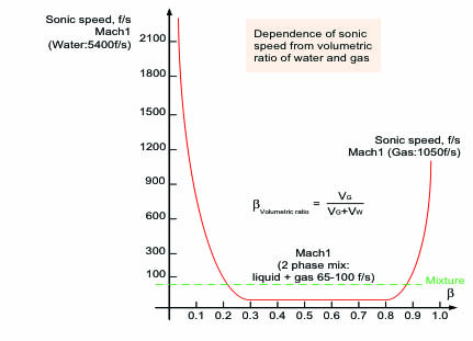
Fisenko demonstrated that uniform two-phase flows have more compressibility than the flows of pure gases. Hence, it is possible to have more effective conversion of thermal energy into mechanical work in uniform two-phase mixtures, especially in the transonic or supersonic modes. The optimized internal geometry of the FD causes the working and injected streams to mix and accelerate, creating transonic conditions and converting a minute fraction of the stream’s thermal energy to physical thrust (pump head) with the discharge pressure higher than the pressure of the mixing streams. The main reason behind this phenomenon is the high compression of homogeneous two-phase flows. The sonic speed in such systems is much lower than the sonic speed in liquids and gases. As shown in Figure 2, the minimum sonic velocity takes place at the volumetric ratio of the streams of 0.5.
From Figure 2, when there is no liquid, the ratio β equals 1. If there is no gas, the ratio β equals 0. When there is 50% liquid and 50% gas (two-phase flow), the ratio β is equal 0.5 and the sonic velocity is much less than in more extreme ratios of gases or liquids. The equation for sonic speed is:
S2 = k x P / ρ
where k is the isentropic exponent, which is equal to the ratio of specific heats; P is the pressure; and ρ is the density of the medium.
 |
|
2. This chart shows the dependence of sonic speed on volumetric ratio of streams. The speed in feet per second (f/s) is shown on the y-axis, while β represents the liquid-gas mixture ratio. (β = 0 when no gas is present and β = 1 when no liquid is present.) Courtesy: Joseph Technology Corp. |
When the transfer from supersonic flow conditions to subsonic is achieved in the jump, the compressibility of the uniform two-phase flow determined by Mach number depends only on the volumetric ratio β of components in the mixture and does not depend on the properties of gas and liquid in the mixture. This result makes it possible to connect pressure in the jump with the pressure before the jump, and together with the obtained equation of the isentropic exponent, to create a design model for FDs in which it is possible to obtain discharge pressure higher than the pressures of the working and injected streams.
Fisonic Devices vs. Conventional Jet Apparatus’
In typical JAs, an increase in the pressure of the discharged flow occurs due to the transfer of steam energy in the process of its condensation on the cold transported medium. At the basis of the exchange of momentum between the media lies the mechanism of viscous friction on the interphase interface. Both the process of heat exchange and the process of friction are from a molecular point of view the processes, the relaxation time of which is proportional to the mean free path of molecules.
Heat exchange between the streams in an FD does not occur in the same manner as it occurs in the usual JA. In a JA, the pressure jump in the mixed streams is associated with the condensation shock, that is, with the process, which is accompanied by a change in entropy. Fisenko demonstrated that in FDs this jump can be isentropic. In this case, in the uniform (fog-like) two-phase flow, the momentum exchange mechanism between the phases is based on elastic interaction of gas molecules with the finely dispersed liquid particles, and the pressure jump mode prevails over the heat exchange process.
Similar to FDs, steam injectors were also studied in France, Poland, Japan, and the U.S. The test results agree and demonstrate that under specific conditions the steam injectors can create discharge pressure higher than the inlet pressures of steam and water. The most interesting results are from extensive tests of multistage steam injectors for DCHs. During the tests, researchers observed results similar to the Russian testing of steam injectors in the 1950s, but by optimizing the geometry and operating velocities, the researchers managed to obtain the required temperature parameters and heated the feedwater practically to the steam saturation temperature.
The proposed system appears very promising but requires extensive testing under transient conditions. To date, no studies have been found to indicate that this system was ever implemented in a commercial power plant. Based on available information, it appears that the most practical feedwater system is the system with two DCHs operated in many power plants in Russia.
Applying the Technology
When designing a feedwater system with DCHs, engineers must prevent, in any mode of operation, water induction into the turbine and reversal of steam flow from the DCHs into the extraction lines in the event of a turbine trip. It is a common U.S. practice not to provide check valves in the extraction lines to condenser neck heaters of the closed type. It is also common practice to maintain approximately one foot of water level in the heater for level control purposes. This is considered a satisfactory situation provided that the total energy contained in the heater and extraction lines will not result in a turbine generator over-speed condition should a turbine trip occur.
The appropriate calculation, according to Recommended Practices For The Prevention Of Water Damage To Steam Turbines Used For Electric Power Generation, American Society of Mechanical Engineers (ASME) Standard TDP-1, and Prevention Of Water Damage To Steam Turbines Used For Electric Power Generation: Nuclear-Fueled Plants, ASME TDP-2, must be completed and approved by the turbine manufacturer. Nonetheless, turbine cycle efficiency can be improved and cost of CFWHs decreased by utilizing DCHs in lieu of closed feedwater heaters. However, these gains must be carefully evaluated against the possibility of damage to the turbine generator due to water induction. ■
—Ishai Oliker, PhD, PE is principal with Joseph Technology Corp. (jtcincorp@optonline.net). He has been involved in power plant development and design in the former USSR, Korea, China, and the U.S. for more than 30 years.