It is well-known that a conventional boiler or heat recovery steam generator (HRSG) and related steam turbine have innumerable pieces all working in conjunction to produce the end product of electric power. In today’s competitive power market, every aspect of the steam generation and turbine equipment needs to be monitored for proper operation. Several examples dealing with steam cycle chemistry abnormalities that are rooted in mechanical issues, and mechanical issues that have a superficial appearance to a chemistry-related problem, are presented in this article.
As the number of facilities having a dedicated onsite chemist are becoming fewer with each passing year, it becomes increasingly important for power plant operations, maintenance, and engineering groups to understand the cause-and-effect relationship between water chemistry and the macro-functionality of the boiler, turbine, and balance-of-plant equipment. The payoff to this understanding is detecting seemingly innocuous events that can have a significant effect on heat rate or maintenance costs, ultimately affecting the cost of generation.
Pump Mechanical Seals
The Electric Power Research Institute (EPRI)-recommended maximum condensate dissolved oxygen (DO) for bimetallic and all-ferrous systems are 10 ppb and 20 ppb, respectively. If the condensate system is air-tight, these values should be easily achieved.
Often-overlooked sources of air in-leakage that contribute to elevated DO are the mechanical seals of condensate pumps and heater drain pumps (if so equipped). A mechanical seal consists of two opposing mating surfaces (the rotating face, secured to the pump shaft; and the stationary face, secured to the seal cover flange) that are precision-machined. Under normal operating conditions, the stuffing box in which the seal resides is under pump discharge conditions. The pressurized condensate forces itself between the rotating and stationary faces, which, due to heat of friction, causes it to evaporate and create a steam film that forms the seal against atmosphere. Secondly, a cushion between the faces is created, helping minimize wear.
The seal’s influence on chemistry occurs when the pump is offline. This applies to redundant pump setups with the standby pump, or to heater drain pumps in the scenario of all pumps being offline due to low-load condition. In an offline/standby condition, the stuffing box is under suction conditions—with condensate and heater drain pumps, this is a vacuum condition. In order to keep the stuffing box, and ultimately the process liquid, sealed against atmosphere and prevent oxygen ingress resulting in elevated DO levels, supplemental seal water needs to be applied to the atmospheric side of the seal (Figure 1).
 |
|
1. An assembled mechanical seal is shown here ready for installation on a vertical turbine pump. Courtesy: Kurt Bayburt |
Typically, this seal water comes from an adjacent operating pump (sourced from the common discharge header). Problems can arise from poorly/improperly configured seal water piping, or no seal water at all. Furthermore, if seal water is indeed applied, it must be applied on the atmospheric side. Oftentimes, this is not the case. In many situations, it is applied to the process side (internal to the stuffing box). With substantial vacuum in this area, atmospheric oxygen can still be pulled across the seal face and dissolve in the stuffing box, eventually being pulled into the suction side of the pump.
Applying a very low-pressure/low-flow seal water (5 psig/0.5 gpm) to the atmospheric side of the seal will prevent oxygen ingress. This may require replacing the seal flange cover with one that has proper internal ports and external pipe connections. A discussion with the pump original equipment manufacturer (OEM) would be in order in this case.
For older conventional boiler units with copper-alloy feedwater heaters, the low-pressure heater drain pumps need to be addressed in the same manner as condensate pumps. Typically, this sub-circuit has little, if any, online monitoring equipment. While the vacuum on the suction of these pumps is not as high as condensate pumps, air in-leakage through the mechanical seals can introduce DO that is undetected by normal chemistry monitoring equipment.
Typically, the pump discharges back into the condensate circuit after the gland steam condenser or first feedwater heater, which is downstream of the condensate DO sample point. At the deaerator, the remaining DO has been mechanically removed. The only chemistry-related feedback that would indicate an abnormal condition would be a reduction in hydrazine residual, if hydrazine or carbohydrazide were the reductants of choice, or a change in @T ORP (at-temperature oxidation-reduction potential), if this instrumentation is utilized. A DO analyzer monitoring the heater drain pump discharge would provide valuable feedback as to the purity of the sample, and is a highly recommended addition to the array of sample analysis equipment.
Non-Return Valve Shaft Packing and Seal Water
Used in conventional boiler systems, non-return valves (NRVs) installed in feedwater heater extraction lines prevent flashing of shell-side condensate and subsequent return into the steam turbine in the event of a turbine trip. While high-pressure extractions are well-above atmospheric pressure throughout the turbine load range, the low-pressure extractions can swing into the sub-atmospheric pressure range at lower loads.
This being the case, the NRV swing arm shaft must be packed differently in the location where the shaft protrudes through the body. High-pressure NRVs can simply have multiple rows of packing rings in the stuffing box, which prevent extraction steam from escaping. Low-pressure NRVs, however, must have seal water piped into the stuffing box (Figure 2), as well as a lantern ring installed with the packing rings. This prevents air in-leakage into the extraction piping during low-load conditions.
 |
|
2. A typical non-return valve is shown here with seal water supplied to the shaft packing. Courtesy: Kurt Bayburt |
This seemingly small source of air ingress can have a significant impact on the DO of the heater drain pump discharge. Although a majority of the air will be removed through the feedwater heater vent piping back to the main condenser (provided the vent line is open), there will be some fraction that will dissolve in the condensate. There will also be a cumulative effect, if there are multiple feedwater heaters operating at sub-atmospheric pressure.
The preceding two examples of uncontrolled air in-leakage have long-term operational effects related to corrosion and metal transport. Operating outside of the EPRI DO guidelines will likely result in increased metal transport, leading to equipment damage (copper removal from feedwater heaters, causing tube leaks) or premature boiler cleanings (increased iron/copper deposition on steam generator tubes, causing reduced heat transfer).
Condenser Liquid Ring Vacuum Pump Performance
The liquid ring vacuum pump is a relatively simple piece of equipment, but plays a major role in the efficiency of the steam turbine. Typically, the skid (Figure 3) consists of the vacuum pump proper along with a heat exchanger, which is used to cool the internal compressant seal water (condensate or another high-purity water source) using an external open- or closed-loop cooling system. The seal water gains heat as it is pumped/sprayed into the inlet of the vacuum pump and compressed, creating the internal seal ring. Also, the moisture-saturated air that is removed from the condenser contains heat that increases the water temperature.
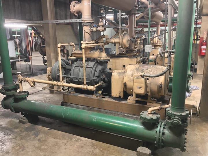 |
|
3. A typical vacuum pump and seal water heat exchanger skid is shown here. Courtesy: Kurt Bayburt |
In order for the vacuum pump to function properly, the seal water temperature must be below the saturation temperature at the condenser operating pressure. If it is not, the seal water will flash inside the vacuum pump, causing loss of the liquid seal ring and ultimately loss of vacuum. A tell-tale sign of this occurrence is a “knocking” noise coming from the vacuum pump.
To ensure the seal water remains below the saturation temperature, two main components must be present: a cooling water source of sufficiently low temperature and high-enough flowrate, and a heat exchanger capable of efficiently transferring heat from the seal water to the cooling water. Aside from an extremely abnormal condition, the first component should have been specified during the engineering, procurement, and construction period, and always available and in-service. The second component, however, can change over time.
If the cooling water source is from an open recirculating system or once-through system, the heat exchanger can be susceptible to scale formation or micro- and/or macro-biological fouling (such as bacterial slime or mollusks). These heat exchangers should be included in the list of components to be cleaned during scheduled outages.
Unfortunately, the cooling water side of the heat exchanger is typically the only side that sees regular attention. Loss of exchanger efficiency can also occur on the seal water side, showing up as iron fouling as a result of internal vacuum pump corrosion/degradation. When this occurs (Figure 4), a mechanical or chemical cleaning is in order.
 |
|
4. This image shows an example of significant fouling on the seal water side of a seal water heat exchanger. Courtesy: Kurt Bayburt |
It is important to differentiate the situations related to performance losses rooted in cooling water-side fouling versus seal water-side fouling. Cooling water-side issues indicate a larger scope problem due to inadequate chemistry control, whether it be improper/insufficient scale inhibitors or a lacking bio-control program. Other heat exchangers will likely be suffering the same issues, including the main condenser. Consultation with a water treatment vendor should be in order.
By comparison, seal water-side fouling will be isolated to the vacuum pump/heat exchanger in question. To the untrained eye, however, the situation may appear as if there is a fouling/scaling issue in the condenser related to improper chemistry control, as the condenser performance indications will show increased backpressure and TTD (terminal temperature difference), as well as a reduced condenser cleanliness factor (the comparison of the actual heat transfer to the design heat transfer of the condenser). If the troubleshooting efforts go down this path, a significant amount of time and cleaning effort will be consumed with no net gain in efficiency.
Key Performance Indicators
To track efficiency losses over time from the vacuum pump/heat exchanger, a performance monitoring program should be implemented. In such a program, key readings should be taken and recorded at least seasonally. Parameters to monitor include:
- ■ Seal water inlet and outlet temperatures from the heat exchanger.
- ■ Cooling water inlet and outlet temperatures.
- ■ Vacuum pump air flowrate.
- ■ Condenser absolute pressure.
- ■ Steam turbine load.
Using this data, the following indicators are calculated:
- ■ Seal water differential temperature (ΔT).
- ■ Cooling water ΔT.
- ■ Approach temperature, that is, the difference between seal water outlet temperature and cooling water inlet temperature.
- ■ Saturated steam temperature at condenser pressure.
- ■ ΔT between seal water exchanger inlet temperature and saturated steam temperature. (This is a critical performance indicator. If the seal water temperature exceeds the saturated steam temperature, the vacuum pump will begin cavitating, and its capacity will be reduced.)
- ■ Normalized vacuum pump air flowrate (flowrate/turbine MW). A common industry standard is to control air in-leakage to no more than 1 cubic foot per minute (cfm)/100 MW.
Additionally, the vacuum pump will have specifications that aid in determining the root area of performance loss (although they aren’t always listed on documentation, and may require discussion with the OEM). A few of these to gather are design heat exchanger approach, seal water ΔT, seal water flowrate, and maximum rated airflow. It is also important to know the design seal water temperature for the vacuum pump inlet, as the maximum rated airflow is based off this temperature. If the actual seal water temperature is higher than design (which is a common problem), the pump capacity will be reduced. For example, a pump rated at 8 cfm at 68F seal water temperature, may only be able to flow 6 cfm at 80F seal water.
If during performance testing, the heat exchanger approach temperature is found to be considerably higher than design, this is a tell-tale sign that the exchanger is fouled and needs to be inspected. If the seal water is unable to be cooled sufficiently, it will likely be higher than the saturated steam temperature at the condenser pressure, and the pump will begin cavitating and have reduced capacity.
If air in-leakage into the condenser is sufficient enough, the condenser pressure will begin increasing and there will be a noted increase in TTD, which is the difference between the hotwell temperature and the cooling water outlet from the condenser. This effect is a result of the air being trapped in the condenser and causing an insulating effect around the condenser tubes, essentially preventing them from condensing steam and passing the latent heat to the cooling water.
EPRI studies suggest that for every 1.0 in-Hg increase in condenser pressure, the unit experiences a resultant 2.5% efficiency loss. The fuel costs can increase very quickly from this seemingly innocuous issue. Even a simple mechanical cleaning and/or high-pressure water wash of the seal water heat exchanger can yield significant cost savings.
In another testing scenario, the seal water ΔT was found to be above design. This is an unwanted situation, as this is a sign that the seal water recirculation pump’s flow has decreased below design. Although the seal water may have sufficient residence time in the heat exchanger for cooling, there may not be enough flow as it is sprayed into the inlet chambers of the vacuum pump to effectively form the seal ring. These small pumps are notorious for being neglected, and do require periodic attention (rebuild or replace). Should the pump require maintenance/replacement, a rotameter should be added in order to allow quick visual checks on the pump’s health.
Naturally, not all of these examples pertain to each and every steam generating unit. The overarching theme, however, is that regardless of configuration, there are many mechanical systems that dovetail into steam cycle chemistry control, and ultimately affect efficiency and reliability. Understanding these relationships, as well as corrective actions, should be made a priority among engineering, operations, and maintenance personnel. Ultimately, this will lead to more effective troubleshooting and fewer long-term cost implications. ■
—Kurt Bayburt (kbayburt@azgt.coop) is the chemistry manager for Arizona Generation & Transmission Cooperatives.