Liquid fuel storage requirements are based on fuel type, usage, and whether the fuel is “combustible” or “flammable” as assessed by the fuel flash point. This article presents information on applicable design standards for diesel storage tanks, including sizing and installation best practices. In addition, it explains how diesel fuel blending affects its classification and tank vent design.
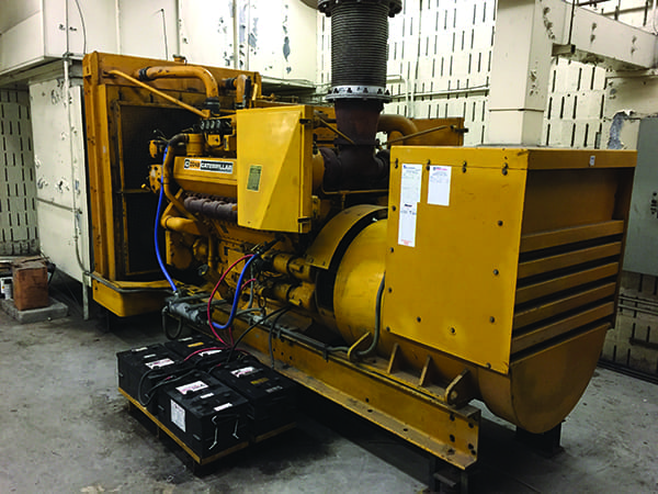
Diesel-fueled generators (gensets) are used for primary power at many electricity generating stations. Furthermore, emergency and standby diesel units are relied upon at many more sites, including coal and nuclear power plants, as well as industrial, commercial, medical, and educational facilities (Figure 1). This means that diesel fuel is stored almost everywhere power is generated.
 |
|
1. Diesel-fueled generators are regularly used to supply emergency power for commercial, industrial, medical, and educational facilities. They are also used at power plants to provide standby power and black-start capability. Courtesy: TAI Engineering |
While it may seem simple to fill a tank with diesel fuel, there are detailed storage requirements outlined in several codes and standards, including the National Fire Protection Association’s NFPA 30 Flammable and Combustible Liquids Code and NFPA 110 Standard for Emergency and Standby Power Systems. There are also a number of best practices for designing safe and reliable diesel fuel storage systems.
Diesel Generator Sets
A basic diesel-fueled genset includes a diesel engine and an electric generator. The mechanical energy provided by the diesel engine turns the generator rotor to produce power in the generator stator windings. The diesel engine itself is an internal combustion engine with various subsystems such as the cooling system, starting system, speed control system, lubrication system, and the fuel system.
The genset typically has a control panel, which is fitted with switches and gauges to operate the generator, such as the start-shutdown controls. In addition, it provides a set of displays for various parameters such as voltage, current, and frequency. The control panel can also include functions to monitor engine parameters such as temperature, speed, oil pressure, and more. The microprocessor within the control panel can be programmed to sense the engine parameters and take corrective action, including engine shutdown.
Diesel Fuel System
In many diesel gensets, an engine-driven fuel pump provides fuel to the fuel injectors via a fuel filter for combustion in the cylinder. The fuel injector is a precision component and has the capability of pumping, metering, and injecting the correct amount of fuel in the combustion chamber. Fuel continually flows in the supply line to the injectors and the excess fuel is returned to the fuel tank through a pressure regulator. The pressure regulator ensures that correct fuel pressure is maintained at the inlet to the injectors.
Another fuel system design utilizes a slightly different arrangement, with the fuel injection pressure being created external to the unit injectors by means of a high-pressure fuel pump. In this arrangement, fuel is not continually circulated through the supply line. Instead, a small amount of fuel is bypassed during fuel injection and this bypassed fuel is returned to the fuel tank. Due to high pressure in the fuel supply, the fuel temperature increases, and the bypassed amount is therefore passed through a cooler before it is returned to the fuel tank.
Diesel fuel temperature must be controlled to a maximum of 66C (150.8F) to ensure that injectors do not plug due to coking and to maintain the fuel viscosity within prescribed limits. Similarly, for cold-weather applications, fuel heaters are required to maintain fuel viscosity and prevent injector plugging due to wax formation.
Diesel Fuel Storage and Supply
According to NFPA 30, storage requirements are based on whether the liquid fuel is “combustible” or “flammable” as assessed by the fuel flash point. The fuel flash point is the lowest temperature at which the fuel will ignite in the presence of an ignition source. NFPA 30 defines combustible liquids as having a flash point equal to or greater than 100F (37.8C) and flammable liquids as having a flash point less than 100F (37.8C).
The flash point of conventional diesel fuel typically ranges between 126F and 204F (52.2C and 95.5C). Therefore, diesel fuel is considered a combustible liquid. It is further classified as Class II if the flash point is less than 140F or Class III if flash point is greater than 140F, depending on the specific fuel.
However, it is important to note that when diesel fuel is blended with ethanol (E-diesel) to reduce emissions, the blended diesel fuel has a low flash point of about 68F (20C). The blended fuel is therefore considered a flammable liquid, requiring management of associated fire and explosion hazards. For simplicity, this article considers only conventional diesel fuel.
|
Biodiesel Clarification In the original article published in the April 2020 issue of POWER, diesel fuel blended with ethanol was incorrectly referred to as “biodiesel.” Whereas, the conventional name for ethanol-blended diesel fuel is “E-diesel.” The wording was changed in this online version of the article on April 2, 2020. The following clarification was also published in the June 2020 issue of POWER magazine. According to a spokesperson for the National Biodiesel Board, “blending ethanol into diesel fuel creates an off-spec fuel according to the ASTM D975 specifications for diesel fuel.” The spokesperson said biodiesel is “a clean-burning alternative to diesel fuel” produced from a broad range of renewable resources including soybean oil, animal fats, and recycled cooking oil. Biodiesel can be used alone or blended with petroleum diesel. “Fuel-grade biodiesel must be produced to strict industry specifications in order to ensure proper performance. Biodiesel blends meet specifications for legal diesel motor fuel (ASTM D7467). Also, B100 (100 percent biodiesel blend) must meet the ASTM definition for biodiesel itself (ASTM D6751),” the spokesperson said. Biodiesel’s flash point is greater than 200F, well above petroleum-based diesel fuel’s flash point of about 125F. “Testing has shown the flash point of biodiesel blends increases as the percentage of biodiesel increases. Therefore, biodiesel and blends of biodiesel with petroleum diesel are safer to store, handle, and use than conventional diesel fuel,” the spokesperson added. However, John Fischer, an engine consultant from Palatine, Illinois, in an email to POWER wrote, “One would be cautioned against the use of biodiesel for the type of application (prime or emergency/standby power) addressed in the article. Because the significant quantity of fuel onsite is seldom consumed quickly and having a ‘food’ sort of aspect—biodiesel will deteriorate more quickly than standard (100%) petroleum diesel. And there is enough to worry about in keeping ‘standard’ diesel clean and water-free.” |
Sizing the Bulk Diesel Storage Tank. The size of a bulk diesel storage tank can depend on a number of factors, including the classification of the emergency power supply system (EPSS) in some applications. The classification is defined in NFPA 110 as the “minimum time in hours, for which the EPSS is designed to operate at its rated load without being refueled or recharged.” For example, a Class 48 EPSS is expected to operate at its rated load for at least 48 hours without refilling the bulk tank. If the rated load consumes 450 liters per hour, the bulk tank should be able to provide 48 hours x 450 liters per hour = 21,600 liters of fuel.
Additionally, NFPA 110 requires the actual size of the bulk tank to be at least 133% of the quantity established by the EPSS class (or the corresponding low-fuel sensor quantity). In addition, the bulk tank should have 5% spare volume above the maximum liquid level, if it is to comply with EN 12285—the European standard.
The bulk fuel storage capacity of 133% provides the ability to test run the emergency diesel for maintenance purposes several times before the tank requires refilling. The tank refilling cycle should be such that the fuel inventory does not drop below the minimum level based on the EPSS classification per NFPA 110.
Bulk Diesel Storage Tank Installation. Bulk tanks can be installed above ground, within a storage tank vault, underground (direct buried), or within a storage tank building.
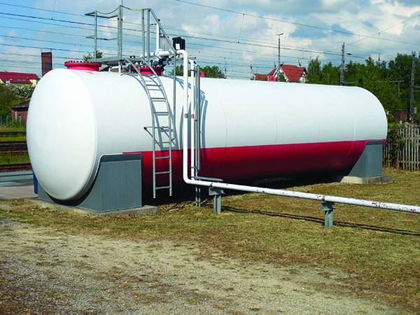
Above-ground tanks (Figure 2) must be provided with emergency relief venting that will release internal pressure, if the tank is exposed to fire. Means for spill control shall also be provided for above-ground tanks.
 |
|
2. An above-ground, secondary containment-type, double-wall tank for spill control is shown here located away from property lines. Courtesy: Pxfuel |
Tanks listed as “above-ground tanks” can be installed within a vault, and the vault can be either above or below grade. Backfill is not permitted around the tank in a vault and sufficient clearance is required around the tank for inspection and maintenance purposes. Vaults should be provided with a means to admit a fire suppression agent, recover liquid spills from vaults, and sound an alarm in case of vapor/liquid release detection.
Underground tanks and piping require external corrosion protection by means of cathodic protection or use of corrosion-resistant material. The base and fill shall be clean, non-corrosive, compacted sand or compacted gravel.
Storage tank buildings are subject to minimum separation distances from property lines, public ways, and important buildings on the same property. Storage tank buildings and structures shall have at least a two-hour fire resistance rating and be equipped with manual/fixed fire control equipment. Discharge of liquid shall be prevented from public waterways/sewers or adjoining property, and all vents shall terminate outside the building.
Design Standards for Bulk Diesel Storage Tanks. For diesel gen-sets, the bulk storage tank is generally an atmospheric tank designed and constructed per the American Petroleum Institute (API) Standard 650 Welded Tanks for Oil Storage. Such tanks are permitted to operate from atmospheric pressure to a gauge pressure of 1.0 psi (6.9 kPa) but must be vented to prevent vacuum. Other design standards may be used but the pressure limits should be checked to avoid distortion of the tank shell during service. The bulk storage tank can also be designed as a low-pressure tank per API 620 Design and Construction of Large, Welded, Low-Pressure Storage Tanks or as a pressure vessel per the American Society of Mechanical Engineers (ASME) Boiler and Pressure Vessel Code Section VIII.
Venting of Bulk Diesel Storage Tanks. Bulk diesel storage tanks should be equipped with a vent line to prevent vacuum formation or overpressure in the tank during drawdown or tank filling, or due to atmospheric temperature changes. The vent pipe shall discharge to a safe space at least five feet away from building openings and at least 15 feet away from powered ventilation air intake devices.
The vent pipe should be sized per API Standard 2000 Venting Atmospheric and Low-Pressure Storage Tanks, but in no case should it be less than 1.25 inches inside diameter. Also, see Table 23.6.2 in NFPA 30 for vent line sizes as a function of vent pipe length and liquid flow. The vent pipe can be fitted with a U-bend and/or a screen to prevent entry of foreign material. However, these devices create flow restrictions, which are aggravated by blockage due to dirt or insect nests. The flow restrictions should be considered in the pressure drop calculations when estimating tank overpressure/vacuum conditions during operation that could otherwise damage the tank shell.
Storage tanks used for ethanol-blended diesel fuel need to be fitted with a flame arrester at the vent pipe outlet. This is because ethanol-blended diesel fuel is a flammable liquid with a low flash point.
Day Tank. The day tank is located between the bulk storage tank and the diesel engine. The fuel is delivered from the bulk storage to the day tank by means of the bulk storage deliver pump. The fuel from the day tank is transferred to the diesel engine by the engine-driven fuel transfer pump, which is mounted on the engine assembly.
The day tank is required when the engine-driven fuel pump is unable to draw fuel from the bulk fuel tank due to distance or elevation issues. The day tank is also used to ensure efficient fuel flow to the engine by eliminating any externally induced pressure head generated by the location of the bulk tank or from the bulk storage delivery pump. The day tank also serves as a heat sink to collect the hot, unused fuel returned from the engine via a cooler.
Use of Gear Pumps for Bulk Fuel Transfer to Day Tank. The fuel transfer pump from the bulk tank to the day tank is generally a positive displacement gear pump located above the bulk tank. When the pump is started, the air in the suction line is removed and a vacuum is created, which provides the lift for the liquid in the tank to rise in the suction pipe. The total suction lift plus the friction head in the suction line should not exceed 15 inches of mercury (inHg, 7.4 psi) for non-volatile liquids. This value progressively reduces further to 10 inHg (5.0 psi) and below for volatile liquids, due to their higher vapor pressure. A foot valve in the suction line is provided to keep the pump primed and ready for service, precluding the need to evacuate air from the suction line when the pump is started. ■
—S. Zaheer Akhtar, PE is a senior process engineer with TAI Engineering based in Owings Mills, Maryland.