Wind turbines are designed to maximize power production based on the predicted wind speeds found at the plant site. However, excessive wind speeds are experienced at times, so it is crucial to limit power generation at those times to avoid spontaneous runaway turbine situations that may cause damage to the turbine rotor or other parts of the driveline or generator. Wind turbine brake systems are a vital safety system. A critical component in the hydraulic braking system is an accumulator, which provides a supplemental flow of hydraulic fluid during emergency braking operations. Diaphragm-style accumulators are standard, although catastrophic failures in the rubber diaphragm are not uncommon. An attractive and more reliable alternative is the piston-style accumulator that is not susceptible to this failure mode.
Authored by Tom Ulery and Jeff Sage of Parker Hannifin
Wind turbines are designed to operate reliably over their typically 20-year design life. That means a typical wind turbine may run for more than 130,000 hours over its lifespan. In addition to reliable operation, owners also demand that a wind turbine have robust safety systems that protect their investment and the technicians who perform routine maintenance on the equipment. This point is particularly important as each turbine normally operates without constant human supervision and the period between maintenance visits by technicians often extends to every six months. Safety systems are expected to provide overall protection of the equipment without operator supervision nor frequent maintenance technician visits.
During high wind conditions, a wind turbine may produce higher than rated power generation, so the rotational speed of the blade rotor must be controlled so that rated power output of the grid-connected generator may be maintained. Should the grid connection be lost for whatever reason, the turbine rotor will immediately begin to overspeed within seconds. Every wind turbine must possess a robust speed control safety system to prevent high rotational speeds during high wind conditions. The turbine braking system is undoubtedly the essential safety system found in a modern wind turbine.
Safety First
There are many safety systems found in modern wind turbines that provide continuous supervisory oversight without human interaction. For example, vibration sensors placed on the driveline alert operators to its condition and, if vibration reaches critical levels, the supervisory system will automatically shut down the turbine. As in other power generation equipment, sensors measure voltage, current, and frequency of the generator, as well as machinery temperatures. Should an overspeed condition or malfunction occur that allows the freewheeling of the blade rotor, overspeed sensors within the safety system will automatically call for aerodynamic braking to slow the blade rotor. Finally, an anemometer measures the wind speed, another critically important component of the wind turbine’s safety system.
All wind turbines use aerodynamic braking for two principal purposes. The first purpose relates to regular turbine operation. Aerodynamic braking controls the power produced by the generator by properly aligning the nacelle into the wind with yaw control and optimizing the blade longitudinal rotation, typically by full-span blade pitch control. The pitch control system, usually located within the turbine hub, rotates the three variable-pitch turbine blades in unison to precisely control the generator speed based on a feedback signal from the generator.
The second purpose of aerodynamic braking pertains to system safety. Should freewheeling in high winds occur, the aerodynamic braking system will turn each rotor blade 90 degrees on its longitudinal axis to minimize lift and maximize drag, effectively “stalling” the blades. The net result is to stop the rotation of the rotor, often within a few rotations. A mechanical brake is engaged when blade rotation stops to secure the rotor when the wind turbine is out of service, typically for maintenance.
Effective Blade Braking
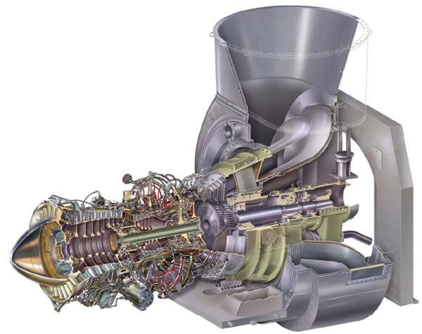
The turbine safety system design is based on the requirement for redundancy. The sensor-based overspeed protection system, for example, is backstopped with a purely mechanical centrifugal brake release system. This concept is not unlike a typical engine generator set where a mechanical centrifugal governor backs up the electronic overspeed controls. On a wind turbine, the safety system backup to aerodynamic braking is a physical disc brake placed on the high-speed gearbox shaft (Figure 1). This approach to stopping the rotor minimizes stress to the blade rotor, tower, or other machinery.
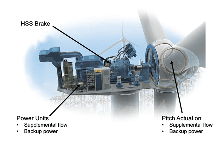
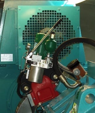
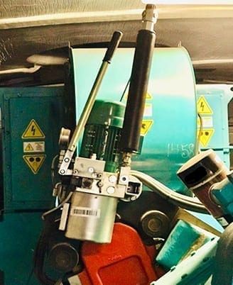
The mechanical turbine brake is placed on the high-speed side of the gearbox before the generator. If the wind turbine rotor turns at 15 rpm, the gearbox will increase the output shaft to 1,500 rpm for the generator. The mechanical brake is actuated by a diaphragm-style accumulator that stores hydraulic fluid under pressure that can actuate a disk brake in the event of an overspeed event during a loss of power (Figure 2).
Potential Failure Modes
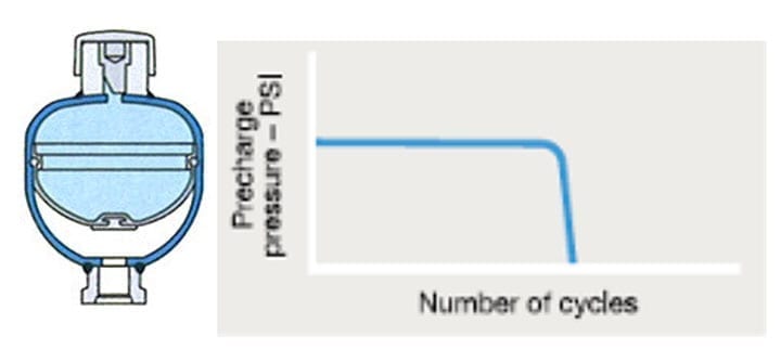
The design of a typical diaphragm accumulator is quite simple. The inlet side of the accumulator is exposed to the pressurized hydraulic oil system. A compressible inert gas, such as nitrogen, fills the top of the accumulator. Separating the two volumes is a flexible rubber diaphragm membrane that compresses the nitrogen to hydraulic system pressure. Should the hydraulic system lose pressure, such as during a power outage or electronics failure, the nitrogen will expand and release the stored hydraulic fluid, which is sufficient to actuate the mechanical brake system and stop the rotating turbine shaft (Figure 3, left).
Field experience has shown that diaphragm accumulators often catastrophically fail at unpredictable times. The failure mode is illustrated in the Figure 3 graph. When a rubber diaphragm ruptures, the pressure in the accumulator immediately dissipates, and the wind turbine critical backup braking system is rendered useless. The rubber diaphragm surface area is gas permeable, and therefore will require more frequent pre-charge maintenance.
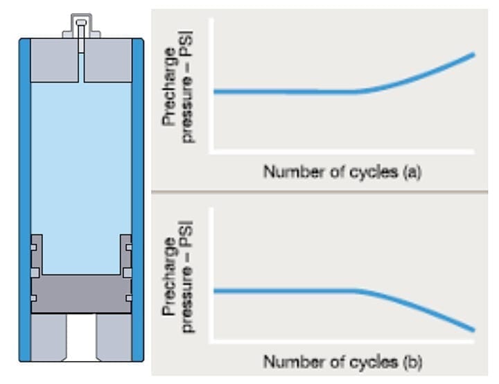
An accumulator has recently proven its worth in more than 1,000 installations over the past year alone. In a piston accumulator, the sealing surface is minimal compared to the cross-sectional area of a diaphragm. Much like the rings that seal a piston between oil and combustion gases, these seals separate the nitrogen charge from the hydraulic oil. Because the surface area of potential gas leakage is significantly less, the amount of pre-charge maintenance is greatly reduced.
The failure mode with the piston accumulator is also significantly less dramatic (Figure 4, left). Instead of an instantaneous failure, as in the case of the rubber diaphragm accumulator, the piston accumulator failure mode is very measured. The first scenario (Figure 4, top right) occurs when the fluid leaks past an accumulator piston, raising the nitrogen pre-charge pressure. The second scenario (Figure 4, bottom right) occurs when the pre-charge gas leaks past the piston, causing the pre-charge pressure to fall. Again, the failure mode is very gradual and never the source of a forced shutdown of the turbine.
The failure mode of the piston accumulator seals occurs over a long period, over millions of cycles, allowing for a manual pre-charge adjustment until the equipment’s scheduled maintenance period. The slow leakage allows for increased machine uptime and prevents costly unscheduled maintenance outages. A ruptured rubber diaphragm, on the other hand, creates an instantaneous failure, resulting in a forced outage, unplanned repair costs, and more extended machine downtime. For this reason, diaphragm accumulators are not the best choice for wind turbine safety systems.
The pre-charge gas is separated from the fluid side of the accumulator by the very small cross-sectional area of the piston seal. The piston-accumulator design minimizes the effect of permeation, and thus requires less nitrogen pre-charge maintenance over time. The rubber diaphragm separates the pressurized gas side of the accumulator from the fluid side with a relatively large cross-sectional diaphragm. This design allows the entire diaphragm to be in contact with the pressurized gas, allowing for a larger area for the gas to permeate through. A typical 1-gallon piston accumulator has 97% less exposed seal surface area than an equivalent 1-gallon rubber diaphragm accumulator.
The cause of permeation is directly related to the rubber compound, the type of gas, the temperature of the gas, the pressure differential, its cyclic duty, and the volume of rubber used to form the diaphragm. The rubber diaphragm accumulators are typically limited to two standard diaphragm compounds, nitrile and hydrin. The piston accumulator has six possible seal compounds with available seal temperature range for –40F to 325F, so there is a seal for every type of hydraulic fluid and temperature requirement.
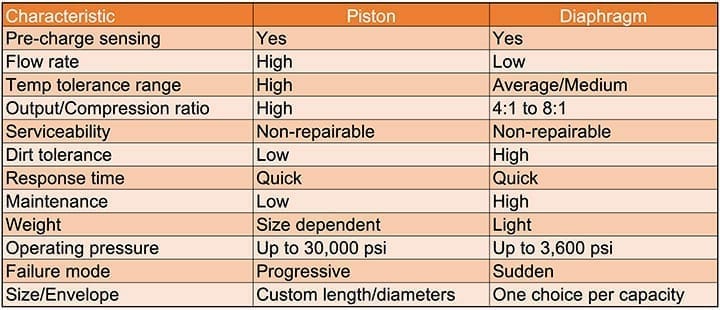
There are other application limitations for the rubber diaphragm accumulators. For example, this style of accumulator is limited to operation in systems with a maximum compression ratio (the ratio of the maximum working pressure to pre-charge pressure) in the range of 4:1 to 8:1. In contrast, the compression ratio of a piston accumulator is unlimited. The technician merely adjusts the pre-charge so that the piston is allowed to ride at mid-stroke, not bottoming out on either end of the accumulator. Other application limitations of the rubber diaphragm accumulators include the limited number of port options and that the orifice limits the design flow rate. The standard piston accumulator allows for multiple sizes and allows for flow rates of eight to 10 times that of diaphragm accumulators. Table 1 illustrates additional technical specifications of the piston and diaphragm design options. Figure 5 presents the installation of a piston accumulator in place of the diaphragm accumulator shown in Figure 2.
Practical Operations
Wind turbine maintenance evolutions are scheduled in advance, and forced outages disrupt that schedule. A rupture in a rubber diaphragm accumulator will signal an immediate turbine forced outage, and it will remain idle until a maintenance team is mobilized to replace the failed accumulator. Depending on maintenance team availability, it would not be out of the ordinary for the turbine to be out of service for five or more days before repairs are completed. Assuming this was a 1.5-MW turbine and that it was operating at the 2019 average capacity factor reported by the Energy Information Administration of 34.9%, then the turbine lost approximately 63 MWh of generation.
Depending on the region where the turbine resides, the lost revenue due to a single wind turbine forced outage would be between $1,200 and $2,000. The cost of emergency maintenance and other related expenses could quickly push the total outage expenses up to $5,000. Given that there are almost 13,000 General Electric 1.5-MW wind turbines in North America alone, the potential loss to the wind industry each year is likely in the tens of millions of dollars.
A wind turbine retrofitted with a piston accumulator will experience a completely different, non-emergency response. The piston accumulator is immune from a catastrophic diaphragm failure, but the piston-cylinder seals will slowly wear over time. Only at that time will the pre-charge pressure slowly begin to drop. Instruments will signal and track the pressure decrease so that a work order can be issued for a maintenance technician to merely “top-off” the pre-charge pressure until the piston accumulator can be replaced at the next regularly scheduled maintenance outage. No muss, no fuss.
—Tom Ulery is business development manager-Renewable Energy with Parker Hannifin and Jeff Sage is product sales manager with Parker Hannifin. This article was prepared with the help of Krishnan & Associates, a specialized energy industry marketing consulting firm.