When needed, surge tanks can provide a critical feature to the hydraulic design of hydropower projects. Principally, they can mitigate the overpressure effects of pressure transients or water hammer and allow turbine wicket gates to be closed faster, reducing generator overspeed after load rejections. However, in normal operation they also have the potential to be detrimental to the control systems of hydropower projects.
In hydraulic reaction turbines, such as Kaplan and Francis machines, there are several ways to mitigate the magnitude of overpressure situations or water hammer. For example, quick-acting pressure relief valves, such as ring follower valves, have been used. In addition to rapid closure of wicket gates, the magnitude of the pressure transient is a function of the length of the water conduit. In short, the faster the closure and the longer the conduit, the higher the overpressure.
Water conduits to impulse turbines, such as Pelton’s, are usually not subject to the need for water hammer protection. This is because they are generally designed with jet deflectors that are spring loaded to drop between the jet of water and the runner buckets, allowing the nozzle valve to be turned off slowly without creating undue pressure transients or allowing significant overspeed of the turbine-generator.
Surge tanks (Figure 1) are the most common means of protecting against excessive water hammer pressure. These are vertical columns of water with the water surface exposed to the atmosphere. They are generally used in the penstock upstream of the turbine, but as close to the turbine as circumstances allow. They have also been used in draft tube tunnels. If the top of the tank is closed to the atmosphere to create a surge chamber, these are called accumulators, but are seldom used in hydropower designs.
 |
|
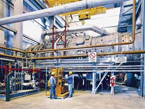
1. A portion of the hydroelectric power plant at Mosul Dam in Iraq is shown here with four accumulators visible in the background. Similar to surge tanks, accumulators protect against pressure transients, mainly caused by the rapid closure of wicket gates. Source: U.S. Army Corps of Engineers |
How a Surge Tank Functions
Surge tanks have the advantage of no moving parts, and therefore, they provide passive protection that is always ready to act. In fact, they act in two different passive manners. When a positive pressure wave reaches the surface of the reservoir, it is reflected down the conduit as a negative wave. This cancels the next upcoming positive pressure wave. In a like manner, the water surface of the surge tank reflects a smaller negative wave back downstream, but sufficient to cancel part of the peak of the upcoming positive pressure wave.
At the same time, part of the flow velocity that is being slowed by the reduced opening between the wicket gates is diverted up into the surge tank and does not contribute to the overpressure. This causes the water surface elevation in the surge tank to rise dramatically. However, this rise is not all due to the diversion, but some is due to recovery of the velocity head and head loss in the penstock. Once these hydraulic oscillations have been instituted in the surge tank, they can continue until dampened out by hydraulic losses into and out of the tank.
Measurement of Surge Tank OscillationsThe measurement of surge tank oscillations is done by the logarithmic decrement: δ = ln ( x1 / x2 ) where ln is logarithm to the base e and x is the amplitude of two successive surges measured from the new steady state water surface. The formula for the equivalent value of the logarithmic decrement is derived as: δ = ln [( a1 + a2 ) / ( a3 + a4 )] where a represents the surge heights sequentially above and below the original steady state water surface. |
In this case, instead of a complete load rejection, if there is a load change through which the turbine-generator remains connected to the grid, the governor remains in control of the unit. This will cause a lesser change in the elevation of the water surface in the surge tank. However, the governor will read this as a change in the head differential across the turbine and seek to readjust the wicket gate opening from the adjustment completed to accommodate the load change. If the governor response time is in synchronization with the hydraulic surge tank frequency, the oscillations will not be dampened, but can be reinforced. This is referred to as hydraulic surge tank instability. The oscillations may grow and remain at a fixed amplitude in “constrained” oscillation (see sidebar). In an extreme case, they may grow until the tank is overtopped, or even worse, until air is sucked into the penstock. A sudden hydraulic unloading of the turbine by air admission in the penstock can be catastrophic.
Types of Surge Tanks
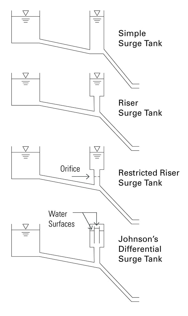
There are several types of surge tanks (Figure 2). The basic differences have to do with the hydraulic losses of fluid entering and leaving the tank. These differences are designed into the passive water hammer protection afforded by the tank to maintain hydraulic stability.
 |
|
2. Four types of surge tanks are shown here. Surge tanks help to maintain hydraulic stability by disrupting resonance waves caused by surges. Source: Lee Sheldon |
The most basic type of surge tank is called a “simple” surge tank. It has a diameter larger than the penstock so that the penstock enters the side of the tank at its base and exits the other side. This type of tank provides the greatest relief to pressure transients but is the least stable.
The second type is called a “riser” tank, which is connected by a smaller diameter pipe between the penstock and the bottom of the surge tank. This type provides less mitigation of the effects of pressure transients, but the additional head loss of fluid entering and leaving the riser and surge tank adds to the stability. Some riser tanks are built with orifice plates in the riser. These are called “restricted riser” surge tanks. They provide even less mitigation to pressure transients but are even more stable.
Finally, there is a class of surge tanks known as Johnson’s Differential or simply “differential” tanks. These are designed with different head losses and elevations for fluid entering and leaving the tank to disrupt the harmonics of hydraulic oscillation.
Criteria for Stability
In the early days of hydropower projects, whenever an unstable surge tank was encountered, it was observed to be most unstable under the following conditions:
- ■ At the lowest head
- ■ Near full power
- ■ Where the turbine efficiency droop was most negative
- ■ Where the penstock losses were the lowest
- ■ Where the conduit losses between the surge tank and the turbine were the highest
In 1910, a German professor in Munich, Germany, D. Thoma, published a paper that was the first to show that turbines with automatic governors could always be stable if the horizontal cross-section of the tank (As,Th) exceeds a certain minimum value. That formula is:
As,Th = L Ap / 2 k g H b
where Thoma’s area (As,Th) equals the length of the water column (L) times the cross-sectional area of the penstock (Ap) divided by a constant for hydraulic losses (k), gravity (g), net head to the surface of the surge tank (H), and resistance factor of the penstock (b). In achieving that derivation, Thoma was forced to assume that generating efficiency was constant with head. Consequently, it was standard practice in Europe to incorporate a safety factor by increasing the Thoma-derived surge tank area 25%. In the U.S., it was common to add 50%.
In the earlier part of the 20th century, G. Evangelisti, an Italian professor of Hydraulic Structures in the University of Bologna, published a paper on hydraulic stability of any type of surge tank. He analytically demonstrated that any hydropower project with a surge tank that is connected to a grid, which also carries more than twice the power from non-surge tank sources, will always be hydraulically stable.
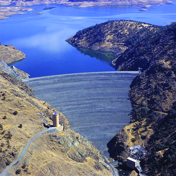
The New Melones Project
A number of years ago, the U.S. Army Corps of Engineers began design work on a hydroelectric project on the Stanislaus River in California. Due to end-of-year budget constraints, it opted to design and build a surge tank for the New Melones hydroelectric project (Figure 3) at the end of one budget year and continue the design of the rest of the project in the following year. It was noted that in the event of a natural disaster this project may be called upon to supply electrical power to a community as an isolated load. Consequently, the surge tank was designed as a restricted riser surge tank, with the Thoma cross-sectional area sized using a 50% safety margin multiplier.
 |
|
3. The U.S. Army Corps of Engineers began building New Melones in 1966, completing the dam in 1978, and the spillway and powerhouse in 1979. New Melones’ surge tank was excavated into the hillside. The large open pipe seen in the foreground of this image vents the surge tank to atmosphere. Source: Bureau of Reclamation |
The Hydroelectric Design Branch (HEDB) of the Corps was tasked with the powerhouse design, including a computer simulation of the entire hydraulic system. This simulation was done with a recently developed computer program called WHAMO, which stands for water hammer and mass oscillation.
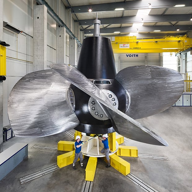
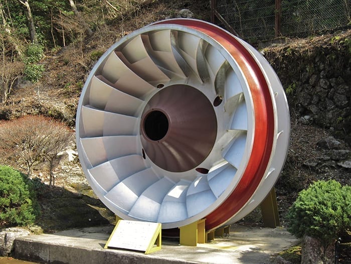
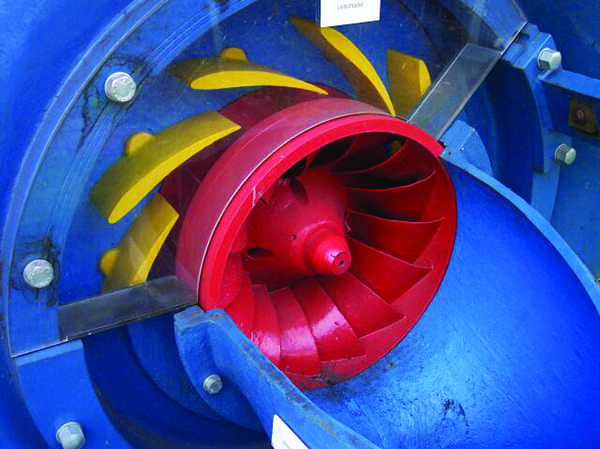
Two different hydraulic Francis turbines (Figure 4) of the proper specific speed were selected to be used in the simulations. After checking maximum and minimum surge elevations for maximum and minimum head losses, a fourth order partial differential equation was used to represent a mechanical governor to check stability, as if the project were serving an isolated load.
 |
|
4. This cutaway view shows the downstream side of a Francis turbine runner with its wicket gates at the full-discharge setting. Source: Creative Commons / Stahlkocher |
The first turbine showed no area of instability. However, the second did show instability and this was in an area where it would be most likely to occur, that is, at minimum head, near full gate, with minimum head losses in the penstock, and maximum head losses in the conduit between the surge tank and the turbine. Because the surge tank had already been built, the Corps was directed to find the turbine performance characteristic that initiated instability and prepare a specification for turbine procurement that eliminated any such possibility.
It took dozens upon dozens of simulations before that unique characteristic could be identified. It was a derivative: the rate of change of the volumetric flow rate with respect to generated power (dQ / dHP). Whenever a simulation was started with a small load change causing that derivative to exceed a value of 0.03 cubic feet per second per horsepower, the surge tank became unstable.
This derivative was investigated further by applying the chain rule of differentiation to the basic formula for fluid power:
HP = Q γ H E / 550
This resulted in:
dQ / dHP = [550 / 62.4 H E] x [ 1 – (HP / E) x (dE / dHP) – (HP / H) x (dH / dHP)]
It was immediately noted that head (H) appears in the denominator of the entire equation. This explains why the lowest head tends to be the least stable. Also, efficiency droop appears as: dE/dHP. Therefore, at any power higher than peak efficiency, the value of dE/dHP becomes negative, making the entire term positive, and contributing to instability. The derivative of the rate of change of head with respect to power (dH/dHP) had not been previously noted as a factor in surge tank stability, but it appears to be a stabilizing influence.
Specifications for Turbine Procurement
For turbine procurement specifications, the Corps of Engineers inverted this discovered derivative, that is, dHP/dQ, or the rate of change of power with respect to flow rate, and gave it the name “demand rate.” The specification was written, “The turbine shall be capable of increasing its output by 33.3 horsepower per cubic foot per second at any head.”
A check was performed of the other turbine used in the simulations, which did not show evidence of instability. It was found that its peak efficiency on the model hill curve was closer to the peripheral speed coefficient for minimum head. When converted to prototype performance values, a demand rate for that turbine did not occur at less than 33.3 horsepower per cubic foot per second anywhere within its operating envelope.
In view of the foregoing, it is less likely that today’s hydropower projects will serve an isolated load (or a grid that has less than twice its power from other surge tank sources). If it does, today’s computer programs can simulate any worst-case scenario to identify the demand rate to be specified in turbine specifications to avoid the possibility of surge tank instability. ■
—Lee Sheldon, PE is a consulting engineer in hydropower and an adjunct professor teaching hydropower engineering, fluid mechanics, and hydraulic laboratory at the Oregon Institute of Technology in Wilsonville, Oregon.