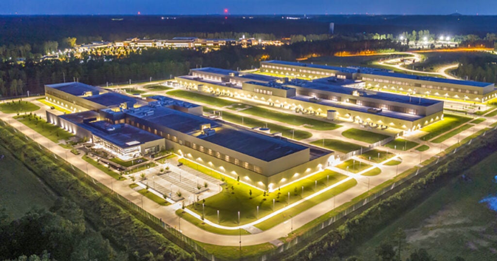
Increasingly fierce competition driven by deregulation and privatization is putting downward pressure on power plant operations and maintenance (O&M) budgets. Recently, lower natural gas prices have pushed natural gas – fired combined-cycle plants higher up in many utilities’ dispatch order in some regions, a welcome change from the twice-a-day cycling experienced by some plants during the past few years. However, with more operating hours comes more interest in plant operating availability, and that means increased emphasis on reliable gas turbine operation (Figure 1).
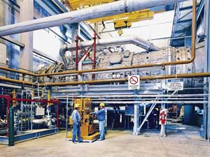
1. Keep costs low. Increasingly fierce competition in the worldwide power generation business keeps the pressure on plant owners to find ways to keep O&M costs low and plant reliability high. Courtesy: Siemens
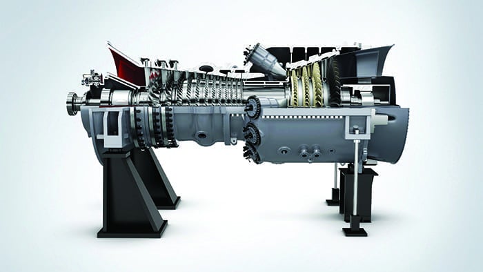
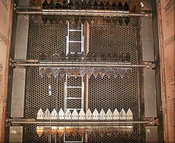
A phenomenon that potentially influences the reliability of gas turbine operation, and therefore the entire combined-cycle plant, is the presence of thermo-acoustic oscillations in the combustion chamber. A "can annular" combustion system arrangement, for example, typically has 16 (more or less) separate can-shaped combustion chambers distributed on a circle perpendicular to the symmetry axis of the engine. In each of these combustors, a burner continuously injects a mixture of fuel gas that is mixed with compressed air to deliver combustion products at a design temperature, pressure, and flow rate to the turbine section to generate the requested electrical power (Figure 2).
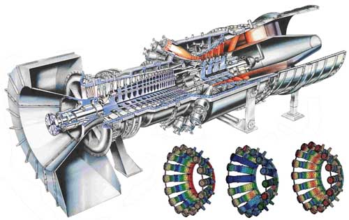
2. Oscillation reaction. The combination of fluid flow, heat transfer, thermal expansion, and acoustic radiation causes combustor oscillations, which may impact operational range and cause internal damage to the turbine. This turbine cutaway is of a Siemens SGT6-6000G, formally known as a W501G, nominally rated at approximately 260 MW. The computational fluid dynamics (CFD) analysis of the combinations of fluid flow, heat transfer, thermal expansion, and acoustic radiation can identify situations where combustion oscillation may cause severe damage. The CFD results illustrate, by the change in colors, azimuthal as well as mixed axial/azimuthal oscillation modes, for which no experimental test setups are possible. Courtesy: Siemens
The combustor oscillations are determined by a feedback cycle that combines the effects of fluid flow, heat transfer, thermal expansion, and acoustic oscillations — a cocktail of effects potentially causing severe engine malfunction and component damage. Some combustion turbine manufacturers have constructed test rigs where prototype combustors are tested and evaluated against a long list of operating regimes and conditions. The disadvantage of prototype testing is that it requires a significant investment of capital and does not provide sufficient flexibility to test alternative designs under additional operating conditions, especially those conditions that cause damaging acoustic oscillations in the combustion system.
Preventing Thermo-acoustic Instability
Siemens engineers have analyzed the complicated relationship and interaction between acoustic performance and thermal heat release and have developed specific measures to prevent thermo-acoustic instability. Sven Bethke, engineer at Siemens Combustion Technology, explains, "Since eigenfrequencies and mode shapes of acoustic pressure are strongly coupled to the stability analysis, the finite-element (FE) mode analysis and the subsequent stability analysis are the main tasks in the thermo-acoustic prediction and evaluation process."
Siemens Power Generation selected LMS Acoustics Simulation Software as the key application for acoustic modeling and simulation because of its widespread use and extensive acoustic simulation capabilities. In the combustion optimization process followed at Siemens, engineers take the output of computational fluid dynamics (CFD) simulations, including steady-state flow velocity, temperature, and fluid properties, as input for acoustic simulations in LMS Acoustics Simulation Software. For these simulations, several different acoustic models are used: an FE model of a single-can combustor configuration; an extended FE model that includes the incoming flow path upstream the burner, turbine vanes, and exhaust passage; and a complete multi-can annular combustor setup.
An important and inherent part of the acoustic FE modeling is the definition of specific boundary conditions, which are determined mathematically or experimentally. Siemens engineers validate the results from acoustic simulation using appropriate tests performed on specifically designed single-can test rigs.
Advances in Combustor Acoustic FE Modeling
The implications of defining boundaries on the FE analysis of a single-can configuration were investigated using LMS Acoustics Simulation Software. The FE model includes the whole combustion chamber, starting at the head end plate and ending at the exit of the transition piece upstream the turbine inlet. The crucial regions through the burner as well as through the termination at the exit of the combustion chamber are characterized by absorbent boundary conditions.
The acoustic boundary condition at the exit of the burner — at the inlet into the combustion chamber — is represented by a specific impedance, which is quantified experimentally using an atmospheric test rig without combustion. At the exit of the combustion chamber, the guide vanes of the turbine — or a vane simulation section (VSS) in the case of test rigs — define the acoustic boundary condition.
Sophisticated mathematical approaches are used to describe the flow field downstream obstacles within the combustor. Compared to the fluid flow behind the vanes, cylinders generate many more vortices, which affect the reflection of the exit boundary condition. The FE model obtained is suitable for analyzing the effects of different impedances, for example, from different types of burners and varying Mach numbers (steady-state flow velocities). The acoustic simulations show that the burner type has a significant impact, while flow velocity in the combustion chamber affects the mode shapes of the acoustic pressure only marginally.
When extending the FE model of a combustor test rig with a VSS — which replaces the vanes of the turbine stages — and a downstream exhaust discharge tube, it became clear that the Mach number cannot be neglected. The presence of narrow passages causes the geometry’s acoustic properties to be influenced by the speed of the flow. Siemens engineers determined the reflection coefficient of the VSS on the basis of the acoustic pressure distribution, obtained by FE simulations performed in LMS Acoustics Simulation Software. The extended FE model is particularly suited to determining the impedance of the boundary upstream of the VSS and its dependency on the Mach number through this section. The results showed a strong dependency on the Mach number through the VSS.
Acoustic Modes of a Can Annular Combustor Setup
To study can-to-can interactions, an FE analysis of a complete multi-can annular combustor configuration was performed. The annular manifold upstream of the turbine inlet interconnects combustion chambers with adjacent units. The absorbent acoustic boundary conditions used to describe the burner and chamber exit areas were defined in the same way as for a single-can model. Simulations in LMS Acoustics Simulation Software show that, besides the axial modes along each single-can combustion chamber, the complete can annular combustor configuration triggers a range of additional acoustic modes. It concerns pure azimuthal and mixed axial/azimuthal modes.
Because there are no test rigs available for measuring the complete can annular combustor configuration, these modes are only predictable by performing acoustic simulations in LMS Acoustics Simulation Software (see Figure 2).
The main reason why Siemens performs these acoustic evaluations is to make sure all potentially hindering or obstructing eigenfrequencies and acoustic velocities are known early on in the design and development process. This enables Siemens engineers to implement specific countermeasures to disturbing eigenfrequencies, for example by developing and installing particular burner outlet extensions and acoustic resonators.
The length of the extensions mounted on burner outlets defines the frequency that can excite the feedback cycle and, hence, affect the risk for combustion instabilities. The installation of these extension units is a quite affordable solution that is particularly useful for suppressing oscillations in the intermediate range of frequencies, typically between 50 and 500 hertz. The sensitivity of these extensions makes this type of countermeasure somewhat harder to tune.
The use of acoustic resonators, which are part of the standard engine design, is another way to influence acoustic eigenfrequencies. This approach is applied very efficiently to delete acoustic signals with shorter wavelengths, such as high frequencies between 1,000 and 3,000 hertz.
The geometry of these resonators can be designed in LMS Acoustics Simulation Software, but a practical way to avoid recurrent FE meshing is by estimating the geometry analytically and, finally, validating the design using LMS Acoustics Simulation Software. The cooling of these resonators prevents hot air from accessing the resonator. Resonators are a very effective means of addressing the problem, although they add complexity and cost while reducing efficiency of the gas turbine as a result of the resonators’ cooling air requirements.
Although the optimization of fluid flow, combustion, and heat transfer remain primary objectives in gas turbine development, more attention is being paid to the interrelations between acoustic performance and operation reliability and efficiency. Sven Bethke concludes, "The combination of virtual prototype simulations with LMS Acoustics Simulation Software and adequate experimental testing allows Siemens to efficiently simulate the impact of specific design modifications and operating conditions on the acoustic performance of gas turbines. The predicted acoustic eigenfrequencies and mode shapes of single-combustion chambers and can-annular combustion systems are essential in optimizing combustor designs and increasing the competitive position of Siemens power generation systems."
— Contributed by LMS (www.lmsintl.com).