ELECTRICAL SAFETY
Protection against arc flash more important than ever
Arc flash may be the greatest—yet least understood—danger in today’s power plant. Its danger is not just the risk of electrocution facing technicians when maintaining switchgear but also the equally deadly concussive blast effects and exceptionally high temperatures that instantly occur when a short circuit occurs. In some instances, all three effects occur in chorus, further dropping the survival rate. (See “Arc flash protection should be job No. 1” in POWER, February 2007 for a special report on arc flash causes and technologies available to improve worker safety.)
The typical arc flash occurs in fractions of a second and without warning when electrical current, designed to move along a particular path, short-circuits either through the air to the wrong conductor or to a ground path. The arc flash that results has been compared to looking directly at the noonday sun, and the temperature of the arc can be as high as that near the surface of the sun—10,000F.
Secondary effects include explosion, with perhaps shrapnel damage, and an intense sound pressure wave. Because power plants have installed high-voltage switchgear in enclosed rooms in recent years, the blast, flash, and temperature effects are further magnified. In older plants where switchgear is sitting in open bays and standing on the turbine room floor gratings, the blast cone can reach out and touch plant staff several floors away (Figure 1).
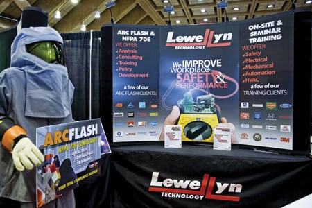
1. Always use protection. Examples of modern arc flash protective equipment were displayed at the 2008 ELECTRIC POWER Conference & Exhibition. Flame-resistant shields and hoods protect the head, face, and eyes against the ultraviolet, infrared, radiant, and convective energies unleashed in an arc flash event. Source: POWER
The cost of arc flash events every year is many millions of dollars in equipment damage, lost production, and lawsuits. But the human toll is without price. A 10-year study by Électricité de France found that arcing caused 77% of all recorded electrical injuries. Similarly, one corporation noted that up to 80% of its electrical injuries involve thermal burns due to arcing faults. The U.S. National Institute of Occupational Safety and Health (NIOSH) tabulated 44,363 electrical-related lost-workday cases from 1992 to 2001. Arc flash burns accounted for 17,101 (or about 39%) of those cases.
Another misconception is that only high-voltage switchgear requires arc flash protection. Not true. I can tell you from personal experience that the heat and blast effects from a standard 480-volt motor control center can cause injuries. According to National Fire Protection Association (NFPA) 70E, the following flash protection boundaries (Figure 2) define the safe working distances from an energized component:
- Up to 750 V: 3 feet
- 750 V to 2 kV: 4 feet
- 2 kV to 15 kV: 16 feet
- 15 kV to 36 kV: 19 feet
- Over 26 kV: must be calculated
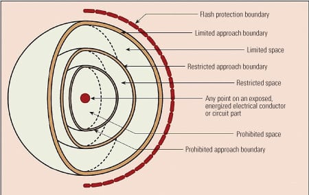
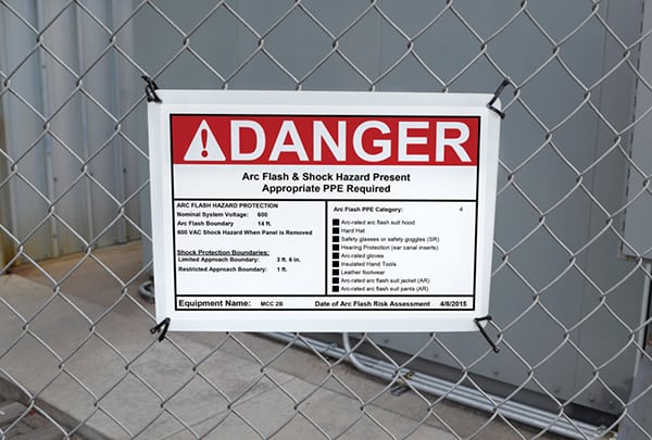
2. Keep your distance. “Flash protection boundary” is defined by the National Fire Protection Association as “An approach limit at a distance from exposed live parts within which a person could receive a second degree burn if an electric arc flash were to occur.” Source: NFPA 70E, Figure A-1-2.3
An often overlooked risk group is thermographers, who must understand these safety standards and be properly outfitted with protective gear when taking readings. They also should be accompanied by a qualified electrician.
Gone are the days when you stuck your hands into any electrical switchgear, regardless of voltage, protected by only a hardhat, safety glasses, and a pair of rubber gloves. Remember, the human heart will begin defibrillating, and soon stop for good, when hit with a relatively miniscule 80 milliamps of current.
New regulations are making arc flash protection from potential electric shock, flash, and blast effects mandatory for plant owners. NFPA 70E now requires protection from arc flash events and also requires a flash hazard analysis. The Occupational Safety and Health Administration (OSHA) has followed suit and has updated its electrical safety procedures to account for arc flash for the first time. The OSHA change was effective August 13, 2007. The OSHA regulations also recognize NFPA 70E and the National Electric Code (NEC) as industry standards that should be followed. Also, check with your insurance carrier, because it’s typically their practice to require conformance with standard industry specifications.
IEEE 1584 provides a guide for performing the arc flash hazard calculations. There is one area in the calculations that many utilities have found to be problematic—how to accurately determine electrical protective device characteristics or relaying in the plant. The response time assumed has a stunning effect on the calculated arc magnitude and duration. Although it’s not required by the regulations, a sensitivity analysis using relay actuation time is easy to perform—many plants have decided to assume instantaneous relay actuation times for the most conservative calculation.
OSHA has cited plant owners after arc flash events under the General Duty Clause, which states: “each employer shall furnish to each of its employees a place of employment that is free from recognized hazards that are likely to cause death or serious physical harm.” The crackdown follows the release of industry statistics showing that the 80% of accidents and fatalities related to electrical work by “qualified workers” are caused by arc flash. Other facilities have been cited under 29 CFR 1910.335 (a)(1)(i), which requires the use of protective equipment when working where a potential electrical hazard exists and/or 29 CFR 1910.132 (d)(1), which requires an employer assessment of all workplace hazards and the use of personal protective equipment.
I suspect many readers also understand that NFPA 70E specifically excludes utilities from the code’s coverage. However, just because a code or regulation has a “loophole,” plant owners shouldn’t hide behind it when worker safety is involved. Chapter one of NFPA 70E states that employers are responsible for providing workplace practices and procedures and employees are responsible for following those procedures.
If your facility does not have an electrical safety program that addresses the extreme dangers of arc flash, suitable protective equipment for workers, and a training program for the equipment and arc flash protection, then you are gambling with your life and the lives of your coworkers.
—Dr. Robert Peltier, PE
COATINGS
Laramie River Station uses new coating technology
Preventing catastrophic failure is the No. 1 priority for power industry mechanical engineers and supervisors. Though a variety of factors can contribute to such failures and ensuing production downtime, engineers unanimously agree that corrosion is the single biggest contributor to these events. The Laramie River Station, located east of Wheatland, Wyoming, implements an aggressive facility maintenance schedule each year and now utilizes new coatings technologies to help protect new and existing assets from the devastating effects of corrosion.
Laramie River Station is one of the largest consumer-operated, regional, joint power supply ventures in the U.S. and is owned by the Missouri Basin Power Project (MBPP). Basin Electric Power Cooperative (BEPC) is one of six electric utilities that own MBPP, and it serves as Laramie River Station’s operating agent. The Laramie River facility is unique in that it delivers power to two separate electric grids: the Eastern and the Western Interconnections. The plant has three coal-based units, each rated at 550 MW, which began operating in 1980, 1981, and 1982. Electricity produced at Laramie River is sent to substations in Wyoming, Nebraska, and Colorado, where it is then delivered to MBPP participants.
Dan Hagel, Basin Electric’s on-site mechanical engineer at Laramie River, is overseeing several coating and lining projects, inspections, and major repair projects being conducted throughout the facility. Hagel’s first exposure to advanced coating technologies came in 2004 during a project to reline the plant’s 10 absorber feed tanks in the wet scrubbers on Units 1 and 2. Ceilcote, the manufacturer that had installed the original system in the tanks nearly 25 years earlier, introduced Hagel to a new generation of epoxy-based lining systems that are formulated with superior environmental and anticorrosion benefits. The 2005 to 2006 relining of these tanks went very smoothly with a coating that has a maintenance life of 20 to 25 years.
Peeling water tanks. In the spring of 2006, Laramie River’s water treatment operations team inspected several of the plant’s contact basins for damage and saw large areas of flaking in the original coal tar epoxy lining. Some flakes were the size of a hand; others were the size of a sheet of notebook paper. Hagel called the coating manufacturer to ask for a recommendation. Ceilcote’s western regional manager, Dave Brysacz, had previously worked on the absorber feed tank installation with the plant’s painting contractor of 15 years, Riley Industrial Services, so together they created a comprehensive maintenance plan to recoat and line the contact basin interiors.
“Using new coating technologies to prevent corrosion-related power failures makes sense,” said Hagel. “If we can extend the maintenance life-cycle of our assets and achieve greater safety and money-saving benefits in the process, then these technologies will have a long-term impact on the power industry at large.”
The installation project will include a total of nine contact basins: six primary and three secondary basins. The primary contact basins used in the plant’s water treatment process combine lime and other chemicals with the lake water and groundwater to help reduce excess calcium and silica in the water (Figure 3). This treated water is then discharged into the secondary basins, where CO2 is added for pH control before it is transferred into storage tanks. Stored water is then pumped through a reverse osmosis system and into the demineralizer system before being fed to the plant’s three boilers and to the six cooling towers serving all three units.
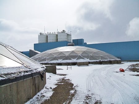
3. Tough work conditions. Winter snow coats the outside of the secondary contact basins. This is a view of the top portion of the concrete sidewalls and aluminum dome. Courtesy: Ceilcote
In order to avoid unnecessary production downtime during the peak summer operating season, only two contact basins would be recoated and lined per year: one during the months of January through March and the other in October through December.
The primary basins measure 85 feet in diameter; secondary basins are 100 feet in diameter. The sidewalls and floor of each basin are constructed from reinforced concrete, while the internal structure is made of carbon steel. Each contact basin is covered with a dome fabricated from aluminum (Figure 4).
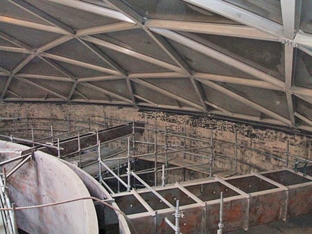
4. Covered basins. This is the interior of the contact basin after grit blasting. The aluminum dome top attaches to concrete sidewalls. Courtesy: Ceilcote
Blast the old coatings. The first installation began on one of the primary contact basins in January 2007. Ceilcote’s technical representative, Tom Moran, met with Riley’s painting crew on-site for refresher training on the proper application of the new tank lining technology. The first step was removal of the old lining system inside the basin’s concrete interior and carbon steel interior structure. The basin’s steel interior was grit-blasted to a white metal finish, 2- to 3-mil profile. In some instances, a second grit blast treatment was needed to remove stubborn patches of the coal tar lining. Next, the reinforced concrete interior received one coat of Ceilcote 680 primer, which was spray-applied and back-rolled to penetrate, strengthen, and seal the concrete. Painters then troweled on one layer of Ceilpatch 610 to fill in pinholes and smooth out any remaining rough spots. Damaged areas of the concrete, in excess of a quarter-inch deep in some areas, were repaired with Corocrete 400 MP.
The internal steel structure was sprayed with a coat of Ceilcote 680 primer, one layer of Ceilgard 664 as a base coat, and a second coat of Ceilgard 664 as a top coat. This solvent-free, moisture-tolerant epoxy coating with flake reinforcement offers superior permeation resistance and corrosion protection to steel and concrete structures in highly corrosive environments (Figure 5).
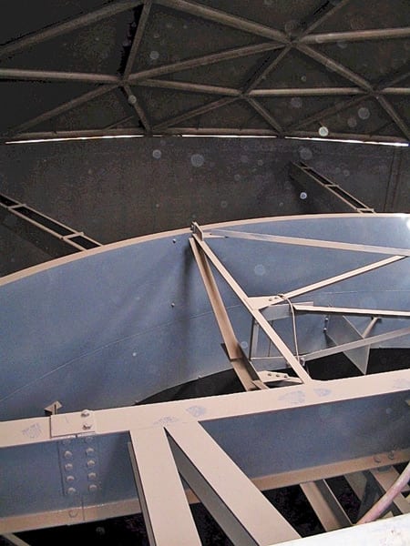
5. Good as new. This is a view of the reaction well structure’s recoated interior and a portion of beam framework that supports the turbine and rake drive after the recoating process was completed. Dust on the framework is from grit blasting the concrete floor after the scaffolding was removed. Courtesy: Ceilcote
Finally, one layer of Ceilcote 68 fiberglass-reinforced epoxy lining was hand-troweled as a base coat for the concrete. This was immediately followed by application of a 1.5 oz. fiberglass mat, which was saturated in via an application of Lining 68BC Resin. The fiberglass mat, in combination with the permanently tough resin, gives this unique moisture-tolerant lining system the excellent crack-bridging capability and tensile strength required for optimal concrete protection. This step was followed by rolling one layer of Ceilcote 664 as a top coat and the application of EJ3 or EJ4 in the expansion joints in the concrete floor (Figure 6).

6. Back in business. In this interior view of a contact basin after relining and re-coating was completed and the basin was back in service, the foreground shows milky water in a reaction well where the lime slurry, sodium aluminate, and other chemicals are mixed. Courtesy: Ceilcote
Labor-intensive process. In all, Riley’s crew of 8 to 10 painters worked 10-hour days, six days per week for nearly three months to complete the surface preparation work and installation of the coating and lining system on one contact basin. Crews will use approximately 2,000 gallons of coatings per basin to achieve an overall film thickness of 120 mils. It is anticipated that completion of the nine contact basins will occur in December 2011.
—Contributed by Dave Brysacz (dave.brysacz@ceilcotecc.com), western regional manager, Ceilcote (www.ceilcotecc.com).
CATHODIC PROTECTION
Protecting power plant pipes: Basics you must know
The risks of corrosion causing catastrophic events at power plants were discussed in “The case for cathodic protection” in POWER, February 2008. Though the oil and gas industries are strictly regulated and must provide protection for all pipelines, that protection stops at the gates to a power plant. Some plant managers don’t realize they have no on-site protection; others may have corrosion protection systems but don’t know how they operate—or if they are even functional.
Cathodic protection is the proven way to stop corrosion and prevent further oxidation on storage tanks and pipelines within a plant. So, educating yourself about the basics of cathodic protection (CP) is a vital responsibility of power plant staff.
Admittedly, cathodic protection maintenance lacks the attraction of maintaining rotating or fired equipment. But it is nonetheless as important. When a turbine sheds a blade or a boiler slags up, there are physical clues to the problem. Underground pipeline corrosion, on the other hand, is hidden from view and easy to overlook when a plant is busy producing electricity. Ignoring cathodic protection maintenance is like going to the dentist when the pain flares in a tooth only to find that the problem has been present for months or years. The result in both cases is greater trauma and cost.
For power plants with old CP systems or limited records, it is wise to have a CP survey completed by a reputable firm. Such a survey will provide evidence of the working level of a CP system (if any exists); recommendations for bringing the survey up to National Association of Corrosion Engineering-approved operation; or certification that the system is operating according the manufacturer’s intent. Then plant managers and power industry executives can be satisfied with the safety of their plant and its people, or it can begin taking steps to protect those assets from calamity.
POWER caught up with Ted Huck (thuck@matcor.com), vice president of sales and marketing at Matcor Inc. and cathodic protection expert, to discuss the fundamentals of cathodic protection.
Basic cathodic protection theory
POWER: What is cathodic protection?
Huck: Cathodic protection is a means to prevent the corrosion of steel.
POWER: What is steel corrosion?
Huck: Corrosion of steel is electrochemical. Steel under normal conditions naturally wants to react with its environment in a reaction process known as oxidation/reduction. It is this reaction that converts steel into iron oxide, or what is commonly called rust. The electrochemical reaction is called a galvanic corrosion cell.
POWER: Do some things corrode faster than others?
Huck: Corrosion rates vary from location to location. Technically, the rate of corrosion is a function of current flow. For example, 1 amp of DC current will consume 20 pounds of steel in one year.
POWER: How does cathodic protection prevent corrosion?
Huck: Cathodic protection is the process of creating a flow of current from a source (the anode) to the structure being protected (the cathode) and shifting the electro-potential of the cathode to a more negative level. This shift in potential prevents the oxidation/reduction reaction from occurring and halts the corrosion.
POWER: How do I apply electric current to the steel surface to stop corrosion?
Huck: That is what we call cathodic protection system design. To use an analogy, to light up a building there are many different types and configurations of lights that could be used. Applying current to the steel structure is a lot like lighting up a building. Anodes placed around the structure are much like light bulbs: The anodes are designed to have current flow from the anode to the structure. How much current flows and how that current distributes are all critical design features.
Galvanic anode systems
POWER: What does “galvanic cell” mean?
Huck: The galvanic cell, named after Luigi Galvani, consists of two different metals connected by a salt bridge or a porous disk between the individual half-cells. It is also known as a voltaic cell or electrochemical cell—a definition shamelessly taken from Wikipedia.org. Batteries are galvanic cells waiting to be connected to some device.
POWER: What are anodes and cathodes?
Huck: “Anode” describes the more electro-negative of the two different metals, while “cathode” describes the more positive of the two metals. Corrosion occurs at the anodic sites. Sometimes, the anode and cathode are different areas of the same structure. The important thing to remember is that milliamps of current can consume a lot of steel over a long period of time.
POWER: What are galvanic anodes?
Huck: Galvanic anodes are specific metals (magnesium, aluminum, and zinc) whose natural potential is less than steel’s. Because these metals are more negative than steel, they can be used as anodes to protect buried steel structures. The anodes are often called sacrificial anodes because they are consumed in the process. A typical home water heater has a sacrificial anode to prevent corrosion of the heater shell.
POWER: So you simply bury enough magnesium, aluminum, or zinc anodes next to the buried structure (a gas pipeline, for example), and the anodes will be consumed while protecting my structure?
Huck: That’s the basic idea. Of course, it is not that simple, and galvanic anodes are quite fickle. The designer has very little design flexibility with galvanic anode systems.
POWER: What do you mean by “very little design flexibility”?
Huck: Galvanic anode systems are limited by the natural potential of the anode material. For example, high-potential magnesium anodes are typically -1.75V, while protected steel is typically above -0.85V, so the differential between the anode and the protected steel is less than 1V DC. For DC circuits, Ohm’s law applies (V = IR), and V is fixed at less than 1 volt. How much current you can achieve will depend on the circuit resistance. If R is too high, then there will not be sufficient current output. If R is too low, then the current output may be too high and the anode may be consumed too fast.
POWER: Can galvanic anodes be used for buried power plant piping applications?
Huck: Yes, they are often used for this purpose. They offer several advantages over impressed current systems, including simplicity of operation and no requirement for external power supply for operation.
POWER: What are the concerns with a galvanic system in a power plant application?
Huck: The big concern is the grounding system. In a power plant, the grounding is extensive, and all of the above-ground metallic structures must be grounded to meet code. Unfortunately, to make a galvanic CP system work, the buried piping must be electrically isolated from the grounding system. This involves installing isolating flange kits at every location where the piping transitions from above grade to below grade.
POWER: What happens if the system loses electrical isolation?
Huck: Grounding networks are designed to provide a low-resistance path to dissipate current. If electrical isolation between the buried piping system and the grounding system is lost, the galvanic anodes’ output will increase significantly, and all the current that the anode produces will be taken preferentially by the grounding network, leaving little or no current to protect the piping systems. The anodes will not be able to protect the piping, and they will be quickly consumed.
POWER: How can a system lose electrical isolation?
Huck: Unfortunately, it is all too easy to lose electrical isolation. For very simple piping systems, isolation can often be maintained by simply testing the isolating flanges on a regular basis. Most power plants, however, do not have simple piping systems and do not regularly test for loss of isolation of buried piping.
POWER: Does that mean galvanic anode systems should not be used in power plants?
Huck: No, but they should not be installed and forgotten. Periodic testing should be performed, and the isolation flanges do require testing and occasional replacement. For most complex power plants, it is almost impossible to ensure electrical isolation, and in those cases galvanic anode systems should be avoided.
Impressed current systems
POWER: What is an impressed current system?
Huck: Unlike galvanic anode systems, impressed current systems have an external power supply that provides current to the CP system and does not rely on the natural potential difference between the anode and structure
POWER: What is the external power supply and what does it do?
Huck: The external power supply is called a transformer/rectifier, or simply rectifier. Most commonly, rectifiers are hooked up to an AC power source and convert the AC power to DC power. (Solar and other power sources can also be used.) The DC power source drives the cathodic protection circuit with current flowing from the positive (anode) to the negative (the structure being protected).
POWER: What are the advantages of an impressed current CP system?
Huck: Unlike a galvanic anode system, which relies purely on the natural potential difference between the anode and the structure and is limited to less than 1 V difference, rectifiers can be sized to provide DC voltages ranging from a few volts to several hundred volts. To use an analogy, galvanic anode systems are like sailboats: They are limited in power. Impressed current systems are like speed boats: They are limited only by the size of the engine.
POWER: Do impressed current CP systems use the same types of anodes?
Huck: No, because they use an external power supply, the anodes can be selected based on their consumption and current discharge capabilities and are not limited to metals whose natural potential is less than that of steel. Impressed current anodes can be designed to provide more current and to last much longer than galvanic anodes.
POWER: What about the isolation of piping from grounding systems?
Huck: Unlike galvanic anode systems, impressed current anode systems can be designed to protect virtually any structure, regardless of whether or not there is grounding present. It is just a matter of providing sufficient current capacity to allow for significant current losses to the grounding system and any other structures that might take current intended for the structures being protected.
POWER: How much current can be lost to the grounding system and other structures when trying to protect buried plant piping?
Huck: That depends on the type of system being proposed. In some cases, 90% or more of the current might be lost to other structures when trying to protect just the piping. The important thing to note, however, is that with a properly designed impressed current CP system it is possible to protect any structure, regardless of the size, soil resistivity, and presence of plant grounding.
Maintenance and testing requirements
POWER: Are galvanic CP systems maintenance-free, since they have no rectifiers?
Huck: A common misconception is that galvanic anode systems require no maintenance, whereas impressed current systems require more maintenance because they require an external power source. This is only partially true. Galvanic anode systems inside a power plant are always vulnerable to the devastating impact of loss of isolation. The loss of isolation not only renders them ineffective in providing cathodic protection to the intended structure, but it also results in their rapid consumption. Both galvanic and impressed current systems require regular testing and inspection.
POWER: How often should I test my CP system?
Huck: Annual testing is strongly recommended for both galvanic and impressed current CP systems.
POWER: What about the rectifiers?
Huck: The rectifiers used for CP systems are generally quite robust and are designed to last the life of the CP system (often 30-plus years). It is recommended that they be checked monthly to ensure that they are still turned on. This involves a visual check of the volt and amp meters and requires no special training or skills.