NUCLEAR PLANT OVERHAUL
Hydro-demolition speeds reactor dome entry
Replacements of the steam generators (SGs) of nuclear power plants have become commonplace since the first one was completed 25 years ago. According to the Nuclear Energy Institute, a total of 132 SG replacements have been performed at 32 plant sites, including 11 in 2006. One of those projects—to replace four generators at Tennessee Valley Authority’s (TVA’s) Watts Bar Nuclear Plant in Tennessee—used a novel technique to make a penetration in the containment dome for moving the SGs in and out. The decision shaved several days from an outage and thus kept TVA from losing millions of dollars of revenue.
Most SG replacement projects place the replacement SG into the containment dome through a penetration in the containment building wall. A typical penetration might be made by cutting a 30-square-foot opening through perhaps 3.5 feet of reinforced concrete and then through a steel liner that is typically ¾-inch thick. This may be typical practice, but it’s not necessarily a cost- or time-efficient way to make a penetration.
To shorten the time needed to replace its four SGs, managers of the Watts Bar plant decided to try a unique but unproven hydro-demolition process to penetrate the containment. The project’s general contractor, Bechtel Power Corp., hired North American Services Group (NASG) and gave the company one year to complete the design, engineering, and testing of a system comprising a hydro-demolition robot and a water containment and treatment facility.
According to Joe Fogarty, senior project manager for NASG, one of the first tasks his team tackled was creating a mockup of the target containment so that a superstructure could be designed to sit atop it. The unusual design of the Watts Bar reactor precluded penetrating its side.
Once the custom hydro-demolition system was ready, NASG used its 20,000-psi water jet to cut two 1,500-ft2 openings in the containment dome. The holes were made just large enough to allow Bechtel to remove and replace four 450-ton steam generators using one of the world’s largest cranes.
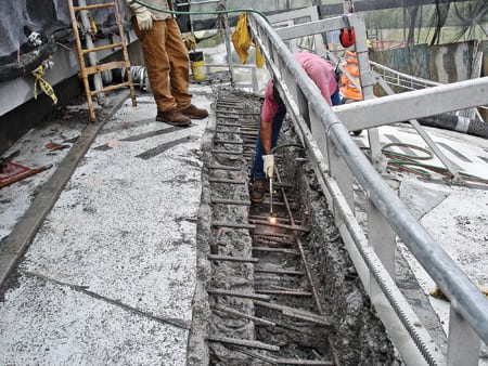
The demolition process began with the installation of a debris barrier system inside the 2-foot-thick concrete dome roof. Next came the installation of a special fixture (Figure 1) designed to keep the water jet perpendicular to the dome roof at all times, regardless of location. The water jet then was used to cut a 30- to 36-inch-wide path about 8 inches deep around the 45 x 22-foot circumference of each concrete section to be removed. The depth of the cut was chosen to leave the steel reinforcing bar (rebar) structure intact.
1. For the super soaker. North American Services Group designed a fixture that keeps the 20,000-psi water jet perpendicular to the containment dome at all times. Courtesy: North American Services Group
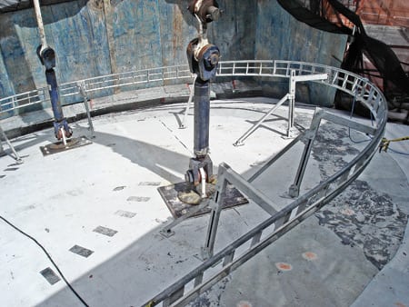
NASG also designed and built two other custom fixtures. One attached to the concrete slabs to facilitate their removal. The other held a 200,000-lb "plug" in place while rebar was cut loose from the dome roof (Figure 2). The hydro-demolition phase of the project was completed in five days, three days ahead of schedule.
2. What lies beneath. An 8-inch-deep cut through the concrete reveals the rebar. Courtesy: North American Services Group
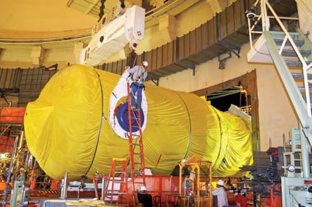
The concrete slabs removed from the top of the containment building weighed over 100 tons apiece. They would challenge any crane, especially at the Watts Bar project because of the height and boom reach required for this project (Figure 3).
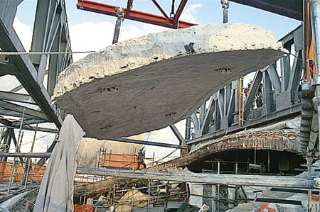
3. Pull the plug. The 100-ton concrete plug was lifted by a crane after the rebar was cut away. Courtesy: North American Services Group
Not taking any chances, TVA reserved one of the world’s largest mobile cranes from Mammoet (www.mammoet.com), perhaps the world leader in turnkey heavy-lift crane rentals. The crane made its way by ship and truck from the Netherlands to Tennessee as more than 100 tractor-trailer loads of individual parts that were then assembled on-site. According to Fogarty, it more than earned its keep, doing double duty on SGs as well as concrete slabs and plugs (Figure 4).
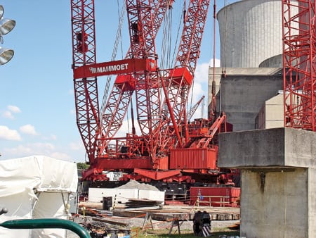
4. World’s largest. A containerized crane was shipped from the Netherlands to handle the very heavy lifting. Courtesy: North American Services Group
In addition to the concrete plugs, approximately 480 cubic feet of concrete rubble were removed. By the time the job was done, the water jet had used about 900,000 gallons of water from the plant fire protection system.
The water-concrete slurry that the hydro-demolition left behind was removed by a high-suction vacuum system sited at the base of the building. The rubble was screened for radiation and periodically transported off-site for disposal in a local landfill. The project’s wastewater was also monitored, treated, and drained per the plant’s NPDES (National Pollutant Discharge Elimination System) permit requirements. The steel liners originally cut from the containment vessel after the concrete sections were removed were rewelded back in place after the new SGs were installed.
Contributed by North American Services Group (www.naisinc.com).
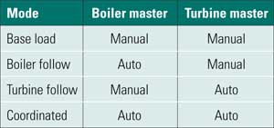
BOILER CONTROLS
Tips for keeping your unit stable
Boiler tuning is a difficult, yet extremely important, task required at all steam plants. It squeezes that last ounce of performance from the overall power production system. A properly tuned boiler maximizes its unit’s ramp rate, its ability to be turned down for low-load operation, its availability, and even unit heat rates and CO2 emissions.
If you were to put together a list of boiler tuning FAQs, the following two items would head the list.
Q: Why is it so difficult to tune boiler controls?
A: Because the controls constitute what is essentially one large, interactive, nonlinear loop that does not lend itself to "automatic" tuning.
Q: Can you improve boiler operation through tuning alone?
A: The unvarnished answer is: sometimes. If the practitioner of this art is very good, boiler control tuning can cover up some sins. However, it is not possible to "tune your way out" of inappropriate control strategies, useless and counterproductive control blocks, and the "garbage" in those blocks. Troubleshooting existing logic is time-consuming but absolutely necessary. In fact, troubleshooting skills are probably more important than tuning skills. It is best to combine tuning with a new control system, appropriate control strategies, good measurements, and small deadband actuators.
Back to basics
If you’re new to the boiler tuning game, the pros will tell you that it’s equal parts art and science. Experience may be the best teacher, but we can get you started with the basics. There are eight general tuning requirements that must be satisfied before detailed system tuning can begin. We’ll first list and briefly explain the eight prerequisites and then present some specific system tuning guidelines.
- A boiler control system must be tuned from the bottom up. You should start with control drives and valves and work your way up to upper loops and feedforwards.
- All measurements must be solid and beyond suspicion. Use of triple-redundant transmitters for drum, throttle, and first-stage pressures is highly recommended. Four transmitters should be used for drum level and furnace oxygen measurements.
- Superheat and reheat thermocouples should be checked for proper response. To check them, at 80% load, move the spray valve by 5% steps. Observe spray and final temperature trends. Thermocouples with temperature trends that show time constants longer than 30 seconds should be removed and checked for good contact with the bottom of the well.
- Check to be sure that a 1% to 2% increase in the control variable (valve, drive) has a fast and repeatable effect on the process variable (feedwater flow, gas flow, air flow, etc.). If a trend shows a 3% to 5% deadband in the control variable, stop tuning that loop and repair the valve or drive. No amount of upper-loop tuning will fix a 5% deadband in the lower loop.
- Measurement and control response should be as fast as can be tolerated and practicable. In many cases, control valve stroking speeds of 2 to 3 seconds are required. This improves the stability and quality of control of the loop under consideration. However, if one loop is affecting and upsetting other loops, a compromise must be reached. In some cases, an excessive speed (for example, of the inlet vanes of an induced-draft fan) can cause major equipment damage, so good engineering judgment is required. However, the rule of thumb is to strive to increase response speed as much as possible.
- Use as little proportional gain, reset, and derivative as needed to achieve adequate quality of control. When a compromise must be made, favor stability over quality of control. A common error is to use excessive reset action, which is deadly to most control loops.
- Feedforward signals are essential to achieving good control stability and quality. The influence of feedforward signals should be calculated from the results of steady-state tests. No more than 80% to 90% of the actual influence should be used for control purposes. For example: If the superheat spray temperature setpoint changes 15 degrees F per 100 psi change of first-stage pressure, use only 12 to 13 degrees F/100 psi as the feedforward signal. Let the feedback control take care of the last two degrees. Otherwise, you could be introducing instability.
- Adaptive tuning is sometimes essential to achieving good stability and quality of control. Consider tuning critical loops at five load points.
Drum level control
The degree of difficulty of drum level tuning depends on the ratio of boiling water storage and steam flow. Tuning of the drum level control on a 600-MW natural circulation boiler with a steam-driven feedpump is extremely difficult. Drum level control on a 30-MW heat-recovery boiler is much more forgiving.
While it’s hard to generalize about drum level tuning, following are some common guidelines:
- A boiler with a relatively small drum might need full-time, three-element feedwater control. This may require an extended range feedwater flow measurement (two stacked transmitters).
- You can make any boiler more stable by lagging the steam flow signal (first-stage pressure) by 15 to 45 seconds. The optimum lag time must be derived by trial and error.
- Consider using a cascade arrangement, with a level controller in an upper loop, and a steam flow as a feedforward to the water flow controller (lower loop). The most important thing is to keep the steam/water flow ratio in balance. This makes the case for using high reset rates for the water flow controller (typically 5 repeats/min). The reset rate for the level controller, on the other hand, should be on the order of 0.1 repeat per minute. The proportional gain of the level controller should be set as low as possible. Balancing steam and water flow is all-important, whereas returning the water back to its normal level as quickly as possible is not only unimportant but also counterproductive. Under extreme upset conditions, overfeeding the boiler may cause severe shrinkage of the water level (because the new water is relatively cold), followed by a severe swell (as the new water heats up) and a high drum level trip.
- Adaptive tuning of the level controller is sometimes essential to achieving good stability and quality of drum level control.
- Tuning of the transition of a steam-driven boiler feedpump through its minimum recirculation flow range can be very challenging on large utility boilers. But it must be done if a minimum unit load of 15% maximum continuous rating (MCR) is desired.
- It pays to spend time optimizing drum level control tuning, especially on large utility boilers. Unstable control of its drum level will destabilize an entire boiler. Often, drum level stability determines a unit’s ramp rate, minimum load, and runback capability (its ability to stay on-line after an upset).
Steam temperature control
Fast and accurate steam temperature measurements are a prerequisite for achieving good steam temperature control. Type E thermocouples in a stainless steel sheath can satisfy that requirement, but only if rust or dirt in the well don’t prevent them from making good contact with the bottom of the thermowell. It is desirable, but not essential, that the thermocouples have a grounded junction. Why? The time constant of the thermowell dominates the time constant of an ungrounded thermocouple. It’s also important to obtain the fastest thermowell that steam conditions allow on a new boiler. If the existing thermowell is too massive, it doesn’t pay to replace it. Instead, it should be compensated for to some extent by derivative action of the temperature controller.
Here are some final tips related to temperature control:
- As with drum level control, the best results usually are obtained with a cascade arrangement. For temperature control, the arrangement would have a spray temperature controller as an inner loop and a final temperature controller as an outer loop.
- The spray temperature controller’s setpoint could include a number of feedforward signals, for example, first-stage pressure.
- Dramatic changes in spray water supply pressure require a spray flow subloop.
- The final steam temperature controller sometimes must be tuned at five load points (adaptive tuning).
- The tuning of the superheat temperature controller must be stable. Otherwise, the entire boiler will swing with a peak-to-peak period of four to five minutes.
Fuel flow control
This loop should be tuned conservatively. Remember, one only needs to move the fuel 2% to 5% per minute. Don’t become preoccupied with maintaining exact throttle pressure; it’s impossible while on load control. During the first 30 to 90 seconds after a load change, the required energy comes from stored energy in the drum. A change in the firing rate will have no effect on throttle pressure for about 90 seconds.
Control of the fuel flow loop should not be made faster than that of the air flow loop (unless you’re using too much excess air, which wastes fuel). For best results, carefully observe fuel and air flow trends during up and down ramps. In theory, they should move in parallel. But in practice, balancing the two usually means having to slow down the fuel controller (less gain, less reset, and no derivative). Like drum and temperature controllers, fuel flow controllers sometimes should be tuned at five load points.
Combustion air control
Don’t use a boiler demand signal as a setpoint for the air flow controller. Instead, use a function generator to convert the boiler demand signal into an airflow demand signal. Doing so will take care of the oxygen curve even before the biasing action of the excess air controller is applied.
Using this approach produces two big benefits: enabling the boiler to operate nearly normally even with oxygen probes out of service and enabling higher unit ramp rates when that is not the case. Again, combustion airflow controllers should be tuned at five load points.
A feedforward signal from the airflow demand signal to the forced-draft fan total position demand is very useful and represents a "belt and suspenders" approach. Note: You cannot use a derivative action in the airflow controller.
Minimum loads and runbacks
With a perfectly tuned large gas/oil-fired utility boiler, it is possible to remain fully under automatic control at 3% of MCR. While that is not recommended for extended periods of time, operating at 15% MCR at minimum load usually is not a problem, as long as drum and heater level controls are well-tuned.
Runbacks must be tuned and tried; otherwise, it’s best to disconnect them. It takes a lot of courage and lost revenues to tune and prove runbacks, but unless that is done a single equipment failure might trip a plant—even a cogeneration plant with multiple boilers and gas and steam turbines. Some big cogen plants have experienced such a domino effect.
When art meets science
Tuning takes time and patience, but it is one of the most important ingredients of a successful plant controls O’M program. The others are use of appropriate control strategies and dealing with accumulated "garbage" in the control logic.
After completing preliminary tuning (making sure each loop operates by itself), the time-consuming effort of fine-tuning (making sure all loops work together over the load range and under all foreseeable upset conditions) begins. This is when it’s time to apply good engineering judgments and make acceptable compromises—the two processes at the heart of boiler tuning.
�Contributed by George Keller, PE, a senior consulting engineer with Burns and Roe Enterprises Inc. He can be reached at gkeller@roe.com.
PLANT MAINTENANCE
Air makes heavy move a breeze
Georgia Power’s 1,549-MW Plant Branch south of Atlanta, near Milledgeville, has the usual complement of power plant equipment and the usual problems of replacing the heaviest and biggest units when they’re ready for retirement. Feedwater heaters are a good example.
According to Gary Barfield, a Georgia Power system engineer, "There are about 32 feedwater heaters in this plant. Since the typical vessel lasts about 30 years, we have to replace one about every five years on average." Sounds like a nice, easy, part-time job, right? Well, it is part-time, but it’s not easy. Each feedwater heater is 30 feet long and six feet in diameter and weighs 60,000 pounds.
Float like a butterfly
Seattle-based AeroGo Inc. (www.aerogo.com) sells air casters that literally float heavy loads on a virtually frictionless film of air 3- to 5-thousandths of an inch thick (Figure 5). Unlike rollers or wheeled equipment, the casters are omnidirectional and take little effort to move and maneuver—a big plus in tight spaces. Available in various styles and load capacities, AeroGo Aero-Casters have been used by shipbuilders, stevedores, and the largest factories. In the modular home industry, they move large structural components through the assembly process.
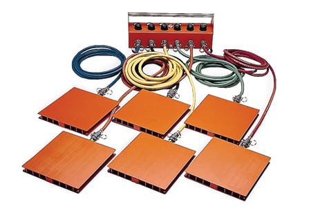
5. Cloud 9. An air caster system can move very heavy equipment and structures. This configuration, with six heavy-duty 36-inch neoprene pads, has a capacity of 240,000 pounds. Courtesy: AeroGo Inc.
Aero-Caster versatility was important to Barfield and Georgia Power. "At Branch, a recent replacement job was a little more difficult because the heater was on what we call a mezzanine floor." Barfield explained. "When you walk out in the plant you’re on the operating floor, which is the first floor. But there’s also a mezzanine floor and a basement, that’s basically underground. To thread the heater onto the mezzanine floor, we had to angle it. It was like trying to run a piece of thread through the eye of a needle.
"Our contractor used the AeroGo air casters to drift the vessel onto the floor [Figure 6] around columns, other pieces of equipment, and valves in the way," Barfield recalled. "The new heater had to be installed exactly where the old one was, within a quarter inch. Once the vessel was in there, the air casters made it easy to move around, you could just bump it just a little bit."
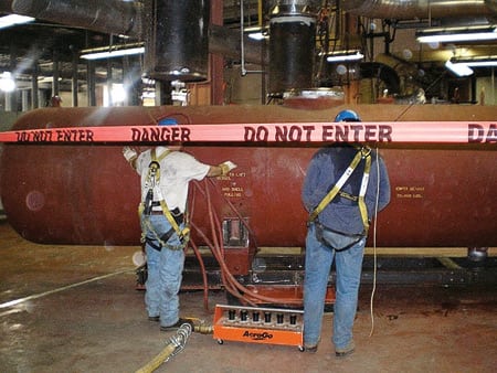
6. No elbow room. Maneuvering a massive, heavy feedwater heater around piping and other obstacles is a big challenge for a maintenance contractor—unless the equipment is floating on air. Courtesy: AeroGo Inc.
Maintain control
Plant Branch hired Cleveland Mechanical Services, a subsidiary of Atlanta-based Cleveland Electric Co., to do the feedwater heater replacement using one of AeroGo’s medium-capacity systems, with a load limit of 240,000 lb. Using rollers to move the heater would have run the risk of overloading the mezzanine floor, possibly weakening it enough to let the unit fall through. The secret to the AeroGo air system is that it spreads the load out over a huge area. In most cases, the load on the floor is no greater than what you’d apply by walking on it.
The other advantage of the system is its maneuverability, which in this case made that "accurate to ¼-inch" placement possible. AeroGo Aero-Casters can move loads around corners, make u-turns, or spin a load around and back it out or in.
The air casters’ maneuverability is matched only by their load capacity. Using them, one person can move a very heavy piece of equipment. With the help of a 3,000-lb forklift, he could move up in weight class to a 160-ton feedwater heater. According to Barfield, all it took to move a heater recently was Harold Edwards’ crew of six (Figures 6 and 7). "And he probably didn’t need quite that many men," Barfield added. "He had an operator on the forklift, and the job of the other guys was to make sure the heater didn’t go anywhere it wasn’t supposed to."
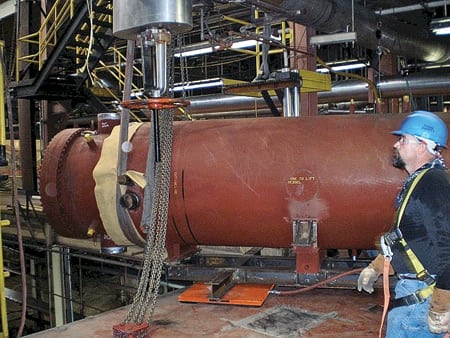
7. Easy rider. The feedwater heater was easily moved to the crane access area by a crew of only five. Courtesy: AeroGo Inc.
Barfield reinforced another point that’s important in today’s liability- and safety-conscious industrial environment: "[Air casters are] a safer way to [move heavy equipment], too. With rollers, something could fall off. And if that something weighs 200,000 pounds, like a tank we moved recently, you’re in big trouble.
"Each air caster we use is rated, I believe, for 40,000 pounds. If one fails, the others can easily pick up the slack. I’ve only used the AeroGo system three times myself, but no caster has ever failed. Georgia Power and Southern Company have hundreds, if not thousands of feedwater heaters and similarly heavy equipment in their many plants. So many other maintenance managers have picked up on the AeroGo system that its use is considered a best practice across our company."
-Contributed by AeroGo (www.aerogo.com)
.