Many coal-fired power stations built before 1980 were constructed using bins, bunkers, and silos designed for relatively easy-handling lump coal. Trends toward using lower-cost fuel and added preparation steps have resulted in harder-to-handle coal and a greater potential for silo flow problems. Coal in portions of these storage systems can remain unrecoverable, leading to a loss of capacity and a stoppage of flow or, in the extreme, to spontaneous combustion and bunker fires.
This article discusses the coal-handling challenges in older equipment and explores options for alleviating flow problems through a case study of Dominion’s Mt. Storm Power Station.
Coal-Handling at Mt. Storm
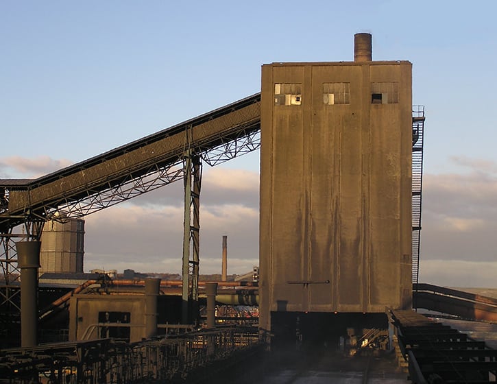
Dominion’s Mt. Storm Power Station, located in the Allegheny Mountains of northeastern West Virginia, has three coal-fired units. The gross generation capacity of each unit is about 560 MW. Units 1 and 2 were built in the 1960s and Unit 3 went into service in 1973. The average daily coal consumption at the station is about 15,000 tons. (Figure 1).
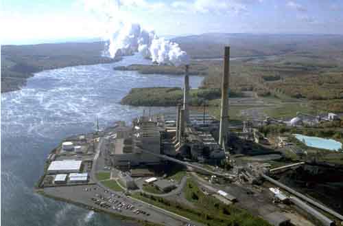
1. Mt. Storm Power Station consists of three similar coal-fired units, all rated at approximately 560 MW. Courtesy: Dominion
The fuel, a locally sourced eastern bituminous coal, is received either by rail or in dump trucks and is transferred to one of two 10,000-ton silos or directly onto outdoor coal storage piles. From the silos and piles, coal is reclaimed and transferred to the bunkers for Units 1, 2, and 3 via two common tripper conveyors. From the bunkers coal is fed to pulverizers and then injected into the boilers.
The bunkers are relatively large, each consisting of a rectangular cylinder that is 131 feet, 8 inches long by 31 feet, 2 inches wide and about 64 feet tall. There are partitions below the rectangular cylinder that divide each bunker into six hoppers.
Before the upgrade project, each hopper consisted of three converging sections with shallow valley (or corner) angles, reducing to a 24-inch square outlet. The lower two pyramidal sections of each hopper had 40-degree (from vertical) valley angles. There was also an inverted wedge-shaped insert in each hopper. The cylinder sections were fabricated from COR-TEN steel, while the hoppers were fabricated from carbon steel. The inside surfaces of the cylinder had previously been retrofitted with a stainless steel plate lining, and the hoppers were constructed with a stainless steel sheet liner (Figure 2).
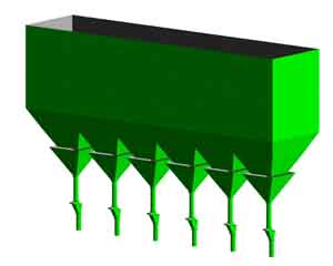
2. Typical, as-built bunker arrangement used by all three units. Source: Jenike & Johanson Inc.
Beneath the outlet of each hopper was a 24-inch bunker valve, followed by a 24-inch-diameter standpipe of varying heights (depending on the unit) and another shutoff valve. A 24-inch table feeder was located below the second valve, which was used to feed a pulverizer below at a controlled rate of about 35 tons per hour (approximately 5,000 tons per day) per unit.
Coal Flow Problems
The bunkers and other handling equipment at Mt. Storm were designed for lump coal. In the early years of the station’s operation, this coal was easily discharged from the bunkers. In response to increased competition, tighter environmental regulations, and reduced coal availability, Mt. Storm was forced to use processed coal that is washed to lower sulfur and ash content. The resulting coal, which can have a significant portion of fines and a high moisture content, has had a greater tendency to develop handling problems, such as arching and ratholing in the bunkers.
These problems were a heavy burden for the station operations personnel. Dave Welch, a project manager at Mt. Storm, said, “We might have 70 feeder pluggages in a shift.” During some periods, the station was unable to keep pace with clearing pluggages, and the units became unstable. “You can’t meet load when steam temperatures and pressures are swinging above the boiler design points and creating wear and tear on the boiler tubes,” Welch said. As a result the station had to burn stabilizing oil, which was very expensive.
A major source of the problems was stagnant coal in the bunkers. The initial approach to improving coal flow from the silos was to install flow-enhancing devices such as vibrators and air cannons, but they were of little help. Station operators typically used hammers and air lances in the hopper sections to clear the obstructions and reinitiate flow. The situation was worst for Unit 3, likely due to the positive pressure mills.
In 2001, Mt. Storm hired Jenike & Johanson (J&J) from Tyngsboro, Mass., to evaluate the fuel-handling system. Project engineers from J&J visited the station during a brief outage of Unit 1 to inspect the empty bunker and review the problems with station personnel. Mike Scott, an engineer from Dominion’s headquarters in Richmond, Va., was involved throughout in identifying the problems and providing project direction. Based on the problem description and an initial review of the bunker design, J&J suspected that ratholing due to funnel flow discharge was the source of the problem.
Solids Flow Patterns
Two primary flow patterns can develop in a hopper: funnel flow and mass flow (Figure 3).
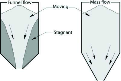
3. Two flow patterns that can occur in a coal hopper: funnel flow and mass flow. Regions where coal is stagnant can become a serious safety and time-consuming maintenance problem. Source: Jenike & Johanson Inc.
In funnel flow, an active flow channel forms above the outlet, with nonflowing material at the periphery. As the level of material in the hopper decreases, layers of the nonflowing material may or may not slide into the flowing channel, which can result in the formation of stable ratholes. In addition, funnel flow can cause caking, provides a first-in/last-out flow sequence, and increases the extent to which segregation impacts the discharging material.
In mass flow, all of the material is in motion whenever any is withdrawn from the hopper. Material from the center as well as the periphery moves toward the outlet. Mass flow hoppers provide a first-in/first-out flow sequence, eliminate stagnant material, and provide a steady discharge with a consistent bulk density and a flow that is uniform and well-controlled. Requirements for achieving mass flow include sizing the hopper outlet large enough to prevent arching and ensuring that the hopper walls are sufficiently smooth and steep to promote flow along them.
A third type of flow pattern is called expanded flow. It can develop when one or more mass flow hoppers are placed beneath a funnel flow hopper. As shown in Figure 4, the lower mass flow hopper is designed to activate a flow channel in the upper funnel flow hopper, which is sized to prevent the formation of a stable rathole. The major advantage of an expanded flow discharge pattern is the savings in headroom. Particularly for large structures, a configuration consisting of a funnel flow hopper above a mass flow hopper results in significantly lower overall height, compared to a mass flow hopper alone. This approach not only reduces capital cost but also facilitates retrofitting existing bunkers by minimizing the additional headroom requirement. The mass flow hopper beneath the funnel flow hopper still has the benefits of discharging material with a consistent bulk density.

4. An example of an expanded flow hopper. Source: Jenike & Johanson Inc.
Modifying bunker hoppers to be completely mass flow, or at least partially so in expanded flow (depending on the size), prevents ratholing and stagnant material. Such an improvement is made by changing the hopper design and/or adding liners that are less frictional. Either way, the hopper outlets must be sufficiently large to ensure that arching is not a concern. Flow properties from material testing can provide the necessary data to use in this design process.
Analysis and Corrective Plan
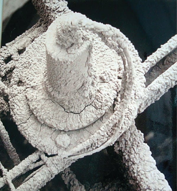
Samples of coal were provided to J&J for flow property testing. Measurements of cohesive strength and wall friction on various bunker surfaces were made using a Jenike Shear Tester (Figure 5) to explore a range of handling conditions, including moisture content, coal temperature, and storage time at rest.
The test results revealed that the coal-handling problems at Mt. Storm were indeed occurring as a result of funnel flow in the bunker hoppers due to the stainless steel liners and their geometry. As a result, ratholes were forming over each outlet, leading to greatly reduced capacity in each bunker and a general instability of coal flow. Additionally, tests found that the 24-inch square hopper outlets were not sufficiently large to prevent arching, particularly due to the coal’s fine and moist nature, and compounded by the presence of collapsing ratholes (which led to overly compacted material at the hopper outlet).

5. Jenike Shear Tester used to determine the flow characteristics of coal. Courtesy: Jenike & Johanson Inc.
J&J recommended bunker modifications to achieve mass flow through a series of wedge-shaped hopper sections, which can allow mass flow with shallower angles than would be necessary for conical or pyramidal hoppers. This type of design is extremely robust in achieving mass flow. Test results indicated that high-moisture coal could adhere to a mild carbon steel surface and even a 304 stainless steel sheet surface with a 2B finish after storage at rest. Therefore, J&J recommended lining the sloping sections with TIVAR 88 Ultra High Molecular Weight (UHMW) polyethylene, manufactured by Quadrant Engineering Plastic Products, but cautioned the station to avoid direct impact of coal on this liner due to its potential for tearing.
To prevent arching and allow easier interfacing with the new hopper sections, the existing 24 inch x 24 inch outlet size had to be increased to a 72-inch width. This change necessitated a replacement of the feeders. Unfortunately, belt feeders could not be used because of the existing short offset between each hopper outlet and the mill below. J&J recommended posimetric feeders, manufactured by Pennsylvania Crusher Corp., which are generally robust and allow the use of a narrow inlet to outlet offset. To investigate further, Dominion personnel visited a power station in Pennsylvania that had retrofitted the feeders and were given a strong positive recommendation.
This change required adding a collection chute beneath each feeder to transition from the elongated discharge area to the 11-inch-diameter inlet to the mill. J&J also designed this chute based on flow properties tests, the converging angle of which was steep enough to allow a bed of coal to slide along its surface after impact.
Another concern with the design was the reduction in the required standpipe height. Standpipes are usually required to provide a pressure seal between the bunker and the mills when the two are at different pressure levels. When the pressure gradient results in gas flow against the solids flow, the potential for arching over the hopper outlet can increase. Given that mills for Units 1 and 2 operated under vacuum, there was less of a concern with this height reduction because the net flow of any leakage air would be downward (in the direction of coal flow). In contrast, the mills on Unit 3 operated at a positive pressure. However, analysis conducted by J&J taking into account the differential pressure and the fuel properties determined that the new standpipe height on Unit 3 did not pose a risk for inducing coal flow interruptions.
Although the coal flow properties favored the use of a conservative design approach that would provide a complete mass flow conversion of the bunker, Dominion’s engineering group determined that the cost of implementing this plan was prohibitive. As a result, J&J was asked to consider an expanded flow option in which only a portion of each hopper would be replaced. After a thorough review, the team found that this approach was feasible and would provide the needed improvement with fewer structural changes but with some loss in silo robustness. Given the dire situation faced by station personnel with the existing arrangement, Dominion agreed that the benefits of this modified approach would greatly outweigh the risks of not implementing the complete solution. Therefore, revised recommendations involving the replacement of only the lower-most pyramidal section of each hopper, beginning at an 11-foot-square cross section, were developed by J&J and submitted to Dominion (Figure 6).

6. Recommended bunker modifications for the expanded flow pattern that was selected by Mt. Storm Power Station. Source: Jenike & Johanson Inc.
Quick Installation
Mass flow hopper sections can experience unusually high loads at their inlets. Hence, it was necessary to calculate the material-induced loads on the bunker walls. J&J determined these loads for various conditions, including the period just after initial fill of the bunker and when complete discharge was taking place. The structural engineering group at Dominion used these loads for the detailed design of not only the new hopper sections but also a reinforcement scheme of the remaining bunker walls at the attachment points. In addition, load calculations for the feeder floor showed that it was nearly overstressed in its current configuration, requiring additional reinforcement to accommodate the heavier posimetric feeders. Because of space constraints below the feeder deck, reinforcing beams were added to the structure.
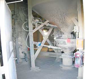
Bidding was conducted on the finished design, and Power Piping Co. of Pittsburgh was awarded the contract. Mt. Storm decided to start work on Unit 2 first due to the upcoming planned outage schedule. Power Piping fabricated the various retrofit hopper sections and collection chutes, and replaced the six existing hoppers and feeders in early 2005. A major challenge in this work was limited access to the material and equipment. Power Piping demolished 159,000 pounds of steel and reinstalled 349,000 pounds of steel; all this work was done with zero recordable accidents and incidences. The work was coordinated with a major boiler outage at Mt. Storm and was completed within an eight-week period (Figure 7).
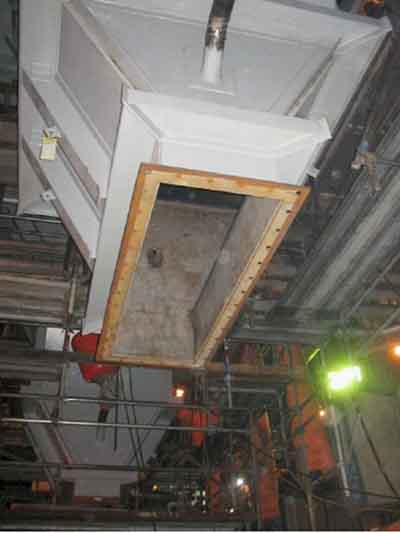

7. Photos during the installation of modified hopper sections (top) and after the installation was completed (bottom). Courtesy: Jenike & Johanson Inc.
Performance Results
After the modifications, Unit 2 ran smoothly for the first few weeks. Afterward, coal started plugging in the chutes below the feeder—a problem that had never occurred at Mt. Storm before the retrofit. After a thorough investigation, it was determined that slight mismatches and gaps at coupled pipe connections were a source of buildup. The behavior of the collection chutes, which tended to direct the coal laterally into these mismatched joints below, compounded the buildup problem. A plan was devised and Dominion technicians replaced additional pipe sections to ensure that the transitions were smooth and free of obstructions. The upgrades have worked perfectly since the feeder problem was resolved.
The benefits of the conversion were quickly apparent. Operators reported more reliable operation of the unit, and the plant’s operations and maintenance technicians were freed from the arduous task of clearing pluggages. Operators requested similar modifications to Units 1 and 3 to be made as quickly as possible. Power Piping was asked by Dominion to complete the modifications to Unit 1 in early 2006 in only four weeks—two weeks less than were used for Unit 2. The project was completed six days quicker than the four-week schedule. By the middle of 2007, Unit 3 had been retrofitted as well.
Once all three units were retrofitted, Mt. Storm was able to fully realize some unexpected benefits. “We eliminated load losses and swings—even eliminated temperature swings we used to have even when we didn’t have feeder pluggages,” said Welch. “Before the conversions, we were happy to just get a ±15-degree swing. After this, we were able to control to ±5 degrees.”
Additionally, the need for stabilizing oil was eliminated. “The fuel department asked us what happened, because we were not buying tankers of oil like we had been,” Welch said. “We’re talking about more than a million dollars a year.”
Finally, Welch noted that parasitic power consumption was also reduced. “The amperage doesn’t swing much any more, and the power needed to bring coal to the furnace is less.”
Dominion is now considering similar changes at other stations.
—Jayant Khambekar is a project engineer and Roger Barnum is a senior consultant for Jenike & Johanson Inc. Keith Geisel is director, business development for Power Piping Co.