Autodegradation is a phenomenon that plagues gas turbines, particularly large frame units. Once the additives in turbine oil deplete, the oil becomes saturated with soluble soft contaminants. As the oil cools, the contaminants come out of solution and form varnish deposits. The contaminants’ solubility at turbine operating temperatures renders electrostatic and agglomeration technologies useless for eliminating varnish problems in these applications (Figure 1).
1. Go with the flow chart. These are the key mechanisms of varnish deposition from gas turbine lube oil. Source: EPT Inc.
Although several commercial products claim to solve the lubricant varnish problem, good operating practices remain the first line of defense (see box). The vendors’ claims are valid for many applications, but not for modern large frame gas turbines. The problem only gets worse when gas turbines are cycled or used for peaking service, as so many are today.
Autodegradation
Autodegradation of oil is defined as the automatic generation of soft contaminants (oil degradation products) in a static, cool body of oil. The lower the quality of a turbine’s lube oil, the greater the impact of autodegradation on its lubrication system. In many cases, varnish deposits form in low-flow areas of the system while high-flow, high-temperature areas remain varnish-free. Varnish removal equipment (electrostatic oil cleaners, agglomerators, or cellulose filters) may be able to keep the oil in the sump very clean, but they cannot stop varnish from forming in low-flow areas.
Inlet guide vane (IGV) valves of turbines that remain sticky even after varnish removal technologies have been added exemplify the problem. Tests often reveal that although the varnish potential rating (VPR) of the fluid in the sump is quite low, the VPR of the oils in the IGV line and in the Moog valve block is very high (Figure 2).

2. Direct deposit. Varnish spool from a liquid fuel pilot valve. Courtesy: EPT Inc.
Figure 3 is a simplified drawing of the hydraulic circuit on a Frame 7 gas turbine. The unit is on turning gear and is equipped with an electrostatic oil cleaner. The colors of the oil lines match the color of their patches in a VPR test. The electrostatic oil cleaner is lowering the varnish potential of the oil in the reservoir, but not of the oil flowing through the hydraulic circuit. The cool, static oil produces deposits throughout the hydraulic system. When the turbine is fired up and its valves try to shift, they stick, causing a trip or fail-to-start condition often referred to as the "Monday morning blues."
3. Only an ounce of prevention. This simplified diagram shows a Frame 7F hydraulic system experiencing autodegradation. The oil with a high varnish potential is prone to forming deposits that can cause unit trips and start-up failures. Source: EPT Inc.
Autodegradation is not necessarily related to lube varnish. In most other applications, autodegradation is not a factor. Among gas turbines, some units have a much greater rate of autodegradation than others. The rate of autodegradation depends largely on the quality of the fluid and the severity of the oil environment, particularly the amount of spark generated in mechanical filters.
Detecting varnish and autodegradation
When an oil degrades, soft contaminants form over time. Soft contaminants are extremely small and a special test is required to detect them. The QSA test is one such test for determining varnish potential. Another, similar test, currently being established by ASTM International, is called membrane patch colorimetry (MPC). In MPC, a sample of oil is first mixed with a solvent to accelerate the precipitation of the varnish components and then it is filtered though a membrane patch. The darker the patch, the higher the varnish potential.
To detect autodegradation, a series of MPC or QSA tests are performed on the same sample. The MPC test is straightforward and fairly easy to perform on-site. A sample of hot turbine oil is tested within 30 minutes of extraction, just as it cools to ambient temperature. The test is then repeated on the same sample after at least 72 hours. If the patch produced by the second test is considerably darker than the one from the first test, autodegradation is occurring. Figure 4 shows how a patch will darken over time. There is an end-point to the autodegradation process at which the patch no longer gets darker. This usually occurs between 72 and 96 hours. In many turbines with severe autodegradation, the full extent of darkening may take place within 3 to 6 hours.
4. Palette of problems. Membrane patches that darken over time indicate an oil with a high varnish potential rating. Source: EPT Inc.
At this point you may ask, "What value does varnish potential testing have if the results are not representative of my turbine at normal operating temperature?" The value of such testing is to quantify the potential for a problem. Time-delayed varnish tests are a very effective and simple way to detect autodegradation. It’s also important to understand that a high VPR may not necessarily indicate imminent danger. For example, if the lube oil of a baseloaded turbine is undergoing autodegradation, the oil may not be static or cool enough to produce varnish deposits.
Fluid formulation
There are two primary antioxidants in most turbine oils: phenols and amines. Their concentration can be measured by a test called the RULER. Autodegradation typically begins once the majority of phenols are depleted below 25% of their original level. In oils that have an amine-only formula or very limited phenolic content, autodegradation begins sooner than in oils with a mix of antioxidants.
For this reason, it’s best to use a turbine oil with both amines and phenols and to monitor their level regularly using the RULER. It’s also advisable to avoid using turbine oil with PANA (an amine additive) because its degradation products lead to deposits. The onset of autodegradation may be a function of the relationship between autodegradation stresses and the level of phenolic antioxidants rather than their absolute level.
Operating conditions are key
EPT Inc. recently completed a study that documented autodegradation problems in 75 turbine oil systems (see table). Sixty-seven of the systems were gas turbines, and eight were steam turbines (none of the latter were found to be affected). The model of gas turbine is identified only when a sufficient number of samples made the data statistically relevant.

A summary of the results of lube oil autodegradation tests performed on 75 prime movers. Source: EPT Inc.
For the purposes of this study, we defined an autodegraded lube oil as having a VPR of >36 (using the QSA test) and a VPR that increased at least 25% from the time the sample was taken until it aged. It should also be noted that in many cases we suspected that autodegradation was a problem before we performed the analysis. In other words, the findings cannot be considered representative of the average varnish potential of any gas turbine manufacturer’s installed base.
The following points on autodegradation can be summarized from the experiments that we have run and data that we have collected:
- As mentioned earlier, autodegradation begins when phenols have been depleted to around 25% of their original level. Oils with no, or low levels of, phenolic antioxidants begin to autodegrade earlier.
- The addition of phenolic antioxidants to oils that have already autodegraded does not stop the process due to saturation with soluble material.
- Electrostatic separation technologies have little or no impact on autodegradation.
- The effect of autodegradation testing on an oil sample can be reversed by heating it to 150F for two hours. This redissolves all of the soft contaminants.
The mechanics of autodegradation
Autodegradation occurs when soft contaminants transition from a soluble (dissolved) state to an insoluble (particulate) state. Imagine the oil as a bucket with a natural capacity to hold dissolved contaminants (Figure 5). When the bucket becomes full, the oil becomes saturated. As more degradation by-products are generated, the bucket overflows and produces insoluble material that can form varnish. When the oil cools, the bucket shrinks in size. The material then overflows this bucket and forms deposits.

5. Temperature-driven transition. Autodegradation results when soft contaminants come out of solution. Source: EPT Inc.
Phenolic antioxidants prevent the formation of soft contaminants by stopping the oxidation process and rejuvenating depleted amine additives. Both phenolic reactions prevent the bucket from filling up by stopping the materials from forming. Once the phenols deplete, the bucket starts to fill and problems begin.
There are two possible reasons why Frame 7FA gas turbines are more susceptible to autodegradation than other units. One is an oil degradation mechanism prevalent in Frame 7FAs: spark discharge from the main lube filters. Virtually every 7FA filter we have inspected showed some evidence of sparking. A spark in the oil releases an incredible amount of energy that kick-starts additive depletion and the formation of many by-products.
A second contributing factor is the high flow rate of the 7FA. High flow rates through filters produce more spark discharge, and their high shearing stresses continually break apart soft contaminants that would agglomerate in calmer conditions. In other gas turbines, larger agglomerates often are returned to the sump as insolubles and removed electrostatically.
Solving the problem
There are three steps that gas turbine operators can take to minimize autodegradation.
Minimize spark discharge. Most gas turbine lube oil filters show some evidence of spark discharge damage (Figure 6). The damage is caused by the buildup of static electricity, both in the oil and on the filters, as high-velocity oil flows through the tight clearances in the filter media. The damage is usually visible only at the microscopic level.
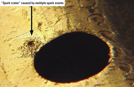
6. Blame it on the heat. The cumulative damage to a last-chance filter core caused by multiple spark events. Courtesy: EPT Inc.
There are some proactive measures that plants can take to minimize spark discharge damage. On some turbines, it’s very easy to switch to using both sides of duplex lube oil filters, which has the effect of cutting the velocity of the oil through them in half. On other units, doing so requires removing a mono-block diverter valve and installing a spool piece and butterfly valves.
Another possibility is to increase the micron ratings of hydraulic and last-chance filters to the maximum allowable by the turbine manufacturer. Along these lines, yet another option is to investigate alternative filtration media. Researchers are developing filtration media that are less prone to maintaining static charges and therefore less likely to produce spark events.
Some plants have removed certain last-chance filters that showed evidence of spark discharge. Before you follow suit, be sure to discuss with your turbine vendor the possible operational impact of doing so. The good news is that minimizing spark discharge will do more than eliminate a source of autodegradation. It also will extend the life of the antioxidants in your turbine oil.
Keep your lube oil warm and moving. Heat tracing and insulating hydraulic piping and valve manifolds can help minimize autodegradation and instances of sticking valves in this part of the lube oil system. When the oil cools, varnish can form where it would not if temperatures were higher. EPT has measured drops of 75 degrees F in the IGV piping of some systems while the turbine was on turning gear/ratcheting. It is advisable to maintain the temperature of the slow-flowing and static oil in the IGV, speed, fuel, and other servo systems as close to the reservoir temperature as possible. Plants that have heat-traced and insulated their IGV lines all the way to and from the IGV valve report dramatic reductions in servo failures and visible varnish. At these plants, oil analysis has shown a reduction in the rate of additive depletion as well.
Another possibility is to install a so-called crossport-relief valve plate, a product co-developed by the GE turbine aftermarket service provider Thomassen Turbine Systems (www.thomassenturbinesystems.com) and Moog Inc. (www.moog.com). This retrofit to Moog servo valves (available in Europe and soon available in North America) allows continual flow through key valve blocks. It has reportedly reduced the impact of autodegradation and varnish deposits. Yet another option is changing the software in the turbine’s control system to allow for regular stroking of the unit’s valves while it is on turning gear.
Reduce levels of soluble contaminants. Minimizing spark discharge and keeping turbine oil warm and moving target the root causes of autodegradation, but they don’t completely eliminate its effects in current turbines. One way to do so is to lower the concentration of soluble contaminants in lube oil systems.
EPT uses its patent-pending ion-charge bonding (ICB) technology to remove soluble contaminants, like acids, from lubricants. Over two decades, ICB has been retrofitted to hundreds of gas turbines and electro-hydraulic control systems. The technology uses carefully chosen and treated ion-exchange resins to remove specific soluble products from lube oil. EPT’s unique blend of resins and delivery methods can selectively remove soluble soft contaminants from turbine oil without disturbing other critical soluble components and additives. Returning to the bucket analogy (Figure 7), ICB treatment removes soluble contaminants from the oil and holds them in a filter, while electrostatic contamination control does the same for insolubles.
7. Double-barreled approach. Working together, two technologies—ion-charge bonding, and electrostatic contamination control—can remove both types of contaminants in lube oil that cause it to autodegrade. Source: EPT Inc.
Dozens of laboratory experiments have studied ICB technology in this application. They are now being correlated with several field trials on Frame 7FA gas turbines and other systems. The patches in Figure 8 represent some typical results. A sample of oil was drawn from the reservoir and split into two equal measures. One was immediately treated with ICB, and the other was left untreated. Both samples were then aged for 14 days under identical conditions and tested using MPC. The whiteness of the ICB-treated patch ("Hot ICB") indicates that all soluble contaminants in it were removed, stopping its autodegradation.

8. Treated vs. untreated. The positive impact of ICB treatment on autodegradation. Courtesy: EPT Inc.
EPT has incorporated ICB technology into its electrostatic contaminant removal system, the ECR 8000 (Figure 9). The system enables removal of both soluble and insoluble materials from turbine lube oil using the same equipment.

9. Varnish buster. EPT’s electrostatic lube oil cleaning system for large gas turbines. Courtesy: EPT Inc.
The author wishes to acknowledge contributions to this article (autodegradation data and independent research) by Brian Thompson of the oil and fluids specialist, Analysts Inc. (www.analystsinc.com).
—Greg J. Livingstone (glivingstone@cleanoil.com) and Jon Prescott (jprescott@cleanoil.com) are certified lubrication specialists and work for EPT Inc. Dave Wooton (davewooton@wooton-consulting.com) has a PhD in chemistry and operates Wooton Consulting.