Users have learned—often, the hard way—that daily cycling reduces the life expectancy of hot components in gas turbines. For years, manufacturers of turbines have designed them to withstand the cumulative wear and damage caused by frequent starts and stops. However, until recently not much attention was paid to designing heat-recovery steam generators (HRSGs) for cycling service.
One reason for this lack of attention has been deficiencies in some codes for designing and manufacturing water-tube boilers and steam generators. For the most part, the ASME’s Section I Power Boiler code and the British standard BS 1113 provide little guidance on designing HRSGs for cycling service. Other European design codes, such as EN 12952 and Germany’s TRD 301, do include practical methods for evaluating boiler and HRSG components for both creep and fatigue. Such information is essential to operating pressure vessels in ways that will extend their useful life.
Over the past decade, vendors and users alike have not only learned plenty about HRSGs’ sensitivity to cycling but also what to do about it. This article discusses several aspects of design and operation that users should be intimately familiar with when specifying a new HRSG for cycling service or when switching one from baseload operation to a daily diet of starts and stops.
Coil flexibility
Before cycling combined-cycle plants became prevalent, it was unnecessary to make HRSG coils flexible in the right places to eliminate or at least minimize low-cycle thermal fatigue. But now it is essential to maximizing HRSG longevity. When older units are switched from baseload to cycling mode, low-cycle fatigue or creep-fatigue often develops rapidly.
Exacerbating the problem, codes such as EN 12952 and TRD 301 provide rules for designing boilers for high-cycle fatigue but none for preventing premature failures as a result of low-cycle creep and fatigue. For HRSGs, low-cycle fatigue is almost always due to unresolved thermal expansion. Non-corrosion-related failures of HRSG tubes, pipes, and headers are typically caused by low-cycle thermal fatigue.
There are two important aspects of coil flexibility to consider: tube-to-tube temperature differentials and superheater/reheater interconnecting piping.
Temperature differentials. In all high-temperature superheaters and reheaters, differences in tube metal temperatures arise as steam is heated from inlet to outlet. In most HRSGs, the rows of tubes closest to the gas turbine (GT) will be the hottest and those nearest the stack the coldest. Tubes at different temperatures expand at different rates. These differences in temperatures and expansion rates are greatest at unit start-up and narrow as full steam flow is established.
There are two options for configuring coils to deal with row-to-row temperature differences. Figure 1 depicts one of them. Here, steam enters the inlet header and is heated by exhaust gas. In the configuration shown, the inlet header at the top of Row #4 is fixed to provide support while the lower headers are allowed to move vertically unrestrained.
1. Beating the heat. This diagram shows a heat-recovery steam generator (HRSG) superheater/reheater coil configuration with one upper header spring-supported. Source: Nooter/Eriksen Inc.
All row-to-row temperature differentials must be absorbed within the coil—by header rotation, tube flexing, and/or axial compression or tension of the tubes. Under transient conditions (such as during unit start-up and shutdown), the mechanical stresses created by the temperature differentials are the highest and are sufficient to produce thermal fatigue. Accordingly, any HRSG whose structural configuration restrains both upper headers from moving vertically would be damaged slightly each time it is cycled. However, the simple addition of a spring to either header for support would enable the tube row to which it is attached to move vertically, decreasing thermally induced stresses by an order of magnitude.
The second superheater/reheater coil-configuration option (Figure 2, p. 40) is one commonly seen in the field. Here, each tube row is supported from above by its own fixed header, and link pipes connect the lower headers to a collector manifold. In this configuration, the maximum thermal stresses are at the bends in the link pipes. This layout does not lend itself well to cycled HRSG operation because components cannot move freely relative to each other. Absorption of row-to-row temperature differentials depends entirely on the flexibility of the coils and the link pipes and rotation of the manifold.
2. Too reliant on flexibility. This superheater/reheater coil configuration has fixed upper and lower headers.
Source: Nooter/Eriksen Inc.
To wrap up this discussion, Figure 3 illustrates some bad and good superheater/reheater coil configurations. None of the three layouts shown in Figure 3a can cope with row-to-row differentials in the magnitude or rate of thermal expansion. In all three cases, the tube rows cannot move freely relative to each other because they are tied together, either by upper and lower headers or a manifold. It’s worth noting that, although these layouts work well in evaporators (where row-to-row temperature differentials are very small), they leave superheater and reheater tubes vulnerable to cycling-induced thermal fatigue.
3. Bad/not bad. At left (3a) are three layouts that constrain free relative movement of tube rows. The three configurations on the right (3b) either facilitate free relative tube movement or maximize row-to-row flexibility.
Source: Nooter/Eriksen Inc.
For contrast, note how the three configurations in Figure 3b either facilitate free relative tube movement or maximize row-to-row flexibility. In the example on the left, the outlet header is supported by a spring, allowing the header to move up or down depending on the temperature difference between the two rows. The other two examples feature long horizontal pipe runs that allow the lower headers to move easily relative to one another.
Interconnecting piping. During HRSG start-up, it is not uncommon for the pipes not heated by gas flow that interconnect superheaters and reheaters to be hundreds of degrees (Fahrenheit) cooler than the coils to which they are attached. In normal operation, the temperature differential between the piping is much smaller and might be accommodated by the piping’s flexibility. Nonetheless, it is important that the layout of interconnecting piping consider the start-up differences. Figure 4 shows a configuration that connects the top of the superheater coil on the right to the bottom of the coil on the left.

4. T spells trouble. Because it is unheated by gas flow, this pipe connecting two superheaters, top to bottom, could be hundreds of degrees cooler than the coils to which it is attached. Such a layout could create higher-than-expected thermal stresses in the pipe, shortening its service life.
Source: Nooter/Eriksen Inc.
Similar arrangements are used for HRSG components such as evaporators and economizers. But these components exhibit fewer thermal-transient problems because the water they contain absorbs thermal shocks, keeping parts at a more constant temperature. Evaporators, however, have been the subject of some concern. During start-up, the tube rows closest to the GT will heat up somewhat faster than the rows further from it. In addition, the entire coil will heat up faster than the downcomer. These temperature differences, typically around 100F, are the concern. Interconnecting piping should be designed with sufficient flexibility to handle the force created by differential thermal expansion.
Component thickness
Most owner/operators of combined-cycle plants insist that their HRSG reach thermal equilibrium quickly enough to avoid lengthening the start-up time of the plant. Assuming that all low-cycle fatigue problems have been resolved, the next concern in this area is the fatigue damage caused either by pressure or by "through-thickness" thermal gradients. Of the two, the latter issue is more important. The magnitude of these thermal gradients is a function of component thickness; the thinner the component, the smaller the thermal gradient and the resulting stress. Consequently, it is considered good design practice to make HRSG parts—such as superheater and reheater headers and the high-pressure steam drum—as thin as possible, to maximize the unit’s heat-up rate.
For an HRSG designer to accommodate the customer’s wishes, however, he must have a pretty good idea of how often the unit is likely to be cycled. If the user doesn’t know or doesn’t provide this information, the vendor has no choice but to use default values for ramp rate and allowable thermal gradients—which may or may not reflect reality.
One design technique used to keep hot headers as thin as possible is to use single-row harp construction, with multiple inlet and outlet nozzle branch connections, as shown in Figure 2. Because there is only one tube row per header, the header’s diameter (and, therefore, its thickness) can be minimized. Unfortunately, such a configuration requires many inlet and outlet nozzles to handle the steam flow.
An alternative technique allows the use of larger headers. Tubes enter a header in a uniform pattern. Most boiler design codes allow the thickness to be calculated using a ligament efficiency approach. With this method, the header must provide all the material necessary to keep the stresses on the primary membrane below acceptable limits. A variation of this approach is to use tube stubs that are thick enough to partially reinforce the hole (Figure 5). This design detail might reduce the header thickness by as much as 30%.
5. Thin is in. A stub-reinforced tube-to-header attachment. Source: Nooter/Eriksen Inc.
Yet another way to minimize the thickness of high-temperature HRSG components such as HP superheaters and reheaters is to make them from stronger materials. If an HRSG will be mated to a gas turbine with exhaust temperatures hotter than 1,100F—for example, an F-class machine—the outlet headers and steam piping of its superheater and reheater sections should use T91/P91 chromium steel, which also has excellent fatigue and creep characteristics.
Tube-to-header connections
The worldwide HRSG user community can’t seem to agree on the method for connecting tubes to headers that is best for cycling service. Europeans, for example, swear by full-penetration weld attachments (Figure 6). But lately, this preference has been challenged by others who warn that the difficulty of making quality full-penetration welds raises the potential for tube leaks. Outside Europe, the consensus is that partial-penetration weld attachments (Figure 7) have proven far more reliable in practice, based on fewer leaks being reported.
6. All the way. European HRSG users prefer full-penetration welds for attaching tubes to headers.
Source: Nooter/Eriksen Inc.
7. Half-way. A partial-penetration tube-to-header attachment. Source: Nooter/Eriksen Inc.
Studies of different joint geometries have shown that during transient conditions, the maximum stresses do not occur at the inside gap of the partial-penetration joint, as previously thought to be the case. When detailed fatigue analyses of full- and partial-penetration joint details are performed, the results are very similar.
It is well known, however, that for steam-service coils operating in the creep range—such as those in high-pressure HRSG superheaters and reheaters—during thermal transients a thicker stub helps minimize the temperature difference between the tube and the header by conducting more heat. In addition to improving the quality of welds, the use of stubbed headers also makes it easier to perform nondestructive examination of welds. For other, less-critical coils such as economizers and evaporators, partial-penetration welds are preferable to full-penetration welds. However, the former are not as good for HP superheaters and reheaters expected to be cycled frequently, compared with thick-stubbed, full-penetration tube-to-header attachments.
Preventing quenching
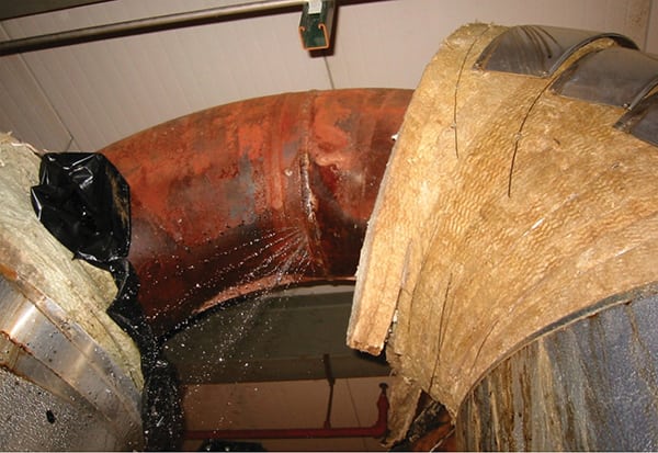
Steam turbine designers and users have long been aware that desuperheater problems can result in turbine water induction. The hot sections of HRSGs are also succeptible to desuperheater problems. It is imperative that any water introduced by improper equipment operation, overspraying, or leakage be detected and removed quickly. Should this happen, the damage from quenching that results is usually severe and may occur as quickly as within one cycle. Figure 8 illustrates the harm caused by desuperheater quenching.
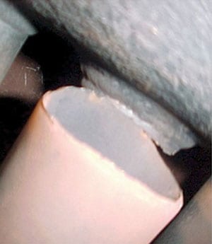
8. Sizzled. This damage was caused by condensate quenching of a desuperheater. Courtesy: Nooter/Eriksen Inc.
For a HRSG, that may be easier said than done. It is nearly impossible to prevent water from contacting hot piping downstream of a desuperheater that has been badly operated, oversprayed, or sprung a leak. In contrast, it is fairly easy to keep water from entering hot coil components upstream or downstream of a desuperheater—by placing condensate drain pots at both locations. The pots are fitted with conductivity probes that detect any water entering them. When the water level reaches an unsafe height, a valve automatically opens, evacuating the water.
Condensate management
Inattention to "fugitive" condensate may not necessarily cause a catastrophic event such as quenching. Condensate that has not been evacuated from HRSG superheaters and reheaters could create large tube-to-tube temperature differentials and proportionately severe thermal stresses.
For combined-cycle plants that are cycled daily, it is normal practice to keep the HRSG hot and at pressure, to minimize thermal gradients and pressure stresses. The National Fire Protection Association requires that the HRSG be purged prior to lighting off the GT to ensure that all fuel gas has been vented. Because the temperature of the GT’s exhaust gas will be below the saturation temperature of steam in various sections during the purge cycle, large amounts of condensate will form. If it is not removed, water will collect in the superheaters and reheaters.
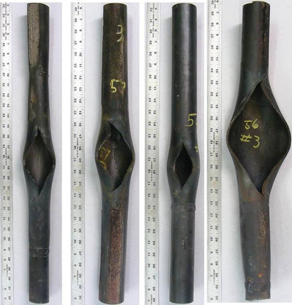
As the evaporator section begins to produce steam, the presence of condensate in the superheaters and reheaters will prevent uniform steam flow. Some tubes will become blocked with condensate, while others will remain clear. This uneven clearing will cause adjacent tubes to heat up at different rates and set up undesirable thermal stresses. In addition, water may be blown into sections that are hot and dry, creating a rapid cooldown or quenching to saturation temperature. Figure 9 illustrates tube buckling caused by uneven clearing.
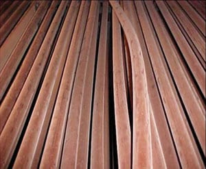
9. Bad start. This buckled tube was caused by uneven condensate clearing. Courtesy: Nooter/Eriksen Inc.
Drain design
Following are four things to look for in the design of drain systems for HRSG superheaters and reheaters:
- The drain on each lower header should be large enough to handle the maximum anticipated amount of condensate. If possible, at least one 2-inch (50-mm) NPS drain should be provided for each header.
- Ideally, drain lines should be higher in elevation than the sump, blowdown tank, or flash tank to which they connect. If this is not possible, "telltale" drains—drains or vent valves designed to continuously monitor leakage—should be provided at low points.
- Drain pots should be used to detect condensate as it is created. The condensate should be removed by automatic means, rather than by manually operated valves. The drain pots should be fitted with conductivity probes (rather than thermocouples) and with pneumatic valves (rather than motor-operated values) for the sake of speed.
- If superheater and reheater drains are routed to a common blowdown tank, be sure that the tank, the manifold, and all piping are large enough to avoid "back-pressuring" the lower-pressure system. If back-pressuring occurs and the higher- and lower-pressure systems are operated simultaneously, condensate could be blown forward into hot sections, causing severe damage.
Feedwater recirculation
During a hot or warm start-up of an HRSG, it is typical for the preheater to be shocked with cold inlet water. After shutdown, while the unit is bottled up, the temperature of lower-pressure sections such as the preheater will rise to match that of other sections. At start-up, there is normally no demand for feedwater, because the drums are swelling.
During these periods, the HRSG components containing feedwater can be steaming or at saturation temperature. A feedwater recirculation system routes water through the feedwater heater prior to start-up. As the HRSG demands water, the colder feedwater can be introduced gradually and mixed with the hotter water already in the feedwater heater. This eliminates or minimizes the shocking.
Auxiliary equipment
As mentioned earlier, it is normal to maintain HRSGs cycled daily at pressure and temperature between each start and stop. There are three ways to do this effectively:
- Use an exhaust stack damper.
- Insulate the exhaust stack and outlet breeching.
- Install a steam sparging system.
Use of a stack damper is the most effective and inexpensive way to prevent cool air from flowing through an HRSG. But insulating the stack and the stack breeching up to the damper would enable heat and pressure to be retained for a much longer period, perhaps for several days.
In most cases, the least effective way to maintain heat and pressure is to install a steam sparging system. Such systems introduce steam into the lower sections of the evaporator coils. Heat from the evaporator then can heat the other HRSG components. Although steam sparging systems work, they can be expensive to install and often have trouble generating enough steam to raise the HRSG’s internal temperature substantially. The technique, however, has proven very effective at keeping HRSGs from freezing. Generally, if your auxiliary equipment budget is limited, you’d be wise to spend your money on an exhaust stack damper and insulation.