A great level of risk is present when operating pressurized systems. Over the years, industry safety concerns have increased with the occurence of catastrophic events. To help prevent further loss and damages, expanded requirements for operations and maintenance (O&M) were added to the ASME Code for Pressure Piping, B31.
Power Piping—ASME B31.1—“Chapter VII Operation and Maintenance” was created in 2007 to prescribe guidelines that promoted early failure detection and overall safety. This was a fundamental change to the scope of B31.1, which up until then was strictly a design code; going forward, it now serves a dual purpose.
Plant management teams have relied on these standards for designing, as well as updating, their maintenance programs. Industry experience shows that combined cycle gas turbine (CCGT) plants owned by investment groups, municipal power companies, and others without large in-house engineering staffs find themselves needing to take action. This is less of an issue for regulated utilities that have established high-energy piping programs, which may address most of the requirements, although some of the failures, including incidents at W.A. Parish and Iatan, occurred at plants operated by regulated utilities.
Incidents Lead to Changes
The latest version of the ASME Power Piping code, published in 2014, has built a foundation from tragic industrial experience. It was the work of committees and experts that drew conclusions from some unfortunate events. Formal amendments were enacted in previous editions of the B31.1 as their work progressed. Two well-known incidents served as catalysts for change.
One of them took place at the W.A. Parish Station in 2003. A cold reheat steam pipe failed and caused a great amount of property damage. Extensive analysis, using such tools as metallographic examinations, computational fluid dynamics, finite element analysis, and fracture mechanics, concluded that fatigue cracking caused the pipeline to explode. In 2007, the Iatan power plant desuperheater attemperator spray line suffered a failure incident caused by flow-accelerated corrosion (FAC). Property damage as well as personnel loss resulted.
O&M Scope and Requirements
The ASME covered piping systems (CPS) O&M program places the responsibility for safe operation and maintenance of power piping on the operating company. Management is charged with implementing a CPS O&M program plan and conducting surveillances, preventive maintenance, and inspection activities that identify potential problems before degradation progresses to component failure or leakage.
A typical scope of a CPS program includes pipe systems that have a 4-inch nominal pipe diameter or greater and additional systems the owners deem important. The most common systems and components are:
■ High-pressure (HP) steam/main steam, including heat recovery steam generator (HRSG) HP steam outlet manifold to steam turbine admission and HP steam bypass from HP steam piping to cold reheat (modern combined cycle plant configurations).
■ Hot reheat (HRH) steam, including HRSG reheat steam outlet manifold to steam turbine admission and HRH bypass to condenser.
■ Cold reheat (CRH) steam, including HP steam turbine nozzle to HRSG reheater inlet manifold, intermediate pressure (IP) steam from HRSG IP superheater outlet to merge with CRH steam, the portion of the HP bypass to CRH that is downstream of the desuperheater spray valve, extractions to gland steam systems, extractions for combustion turbine steam injection, and extractions for condenser sparging.
■ Low-pressure (LP) steam, including HRSG LP superheater steam outlet manifold to steam turbine admission, LP steam bypass to condenser, and LP sparging steam to condenser.
■ Feedwater, including suction from LP drum (or condensate pumps discharge) to boiler feedwater pump nozzle, HP discharge from feedwater pump nozzle to HRSG HP economizer inlet, IP discharge from feedwater pump nozzle to HRSG IP economizer inlet, feedwater supply to fuel gas heater (if installed), feedwater supply to HP steam bypass (to CRH) desuperheater sprays, feedwater supply to CRH/seal steam desuperheater sprays, and feedwater supply to other auxiliary spraywater services.
Chapter VII covers the basic elements that a program should include. From O&M procedures to condition assessment and CPS records, the code highlights the most important facets of the program. Generally, the O&M section focuses on operation modes, documentation, and assessment of degradation. Although each operating company can establish its own O&M procedures, the following aspects shall be covered:
■ Operation of piping systems within design limits.
■ Documentation of system operating hours and modes of operation.
■ Documentation of actual operating temperatures and pressures.
■ Documentation of significant system transients or excursions, including thermal hydraulic events (for example, steam hammers or liquid slugging).
■ Documentation of modifications, repairs, and replacements.
■ Documentation of maintenance of pipe supports for piping operating within the creep regime.
■ Documentation of maintenance of piping system elements, such as vents, drains, relief valves, desuperheaters, and instrumentation, necessary for safe operation.
■ Assessment of degradation mechanisms, including, but not limited to, creep, fatigue, graphitization, corrosion, erosion, and FAC.
■ Quality of flow medium (for example, dissolved oxygen and pH).
■ Documentation of the condition assessment.
The condition assessment details the items to be recorded. Special consideration is given to design temperatures and pressures, pipe material specification, pipe diameters, and the like. The CPS records emphasize the importance of easy access to this information. Documents that extend from the beginning of operation and later modifications are to stay available.
Initiating a CPS Piping Program
Typically, a CPS program incorporates a scope (technical and administrative), degradation mechanisms that affect piping, and overall framework for managing reliability. The technical side covers hanger inspections, Grade 91 and creep evaluations, FAC inspections, thermal shock/impingement assessments, and water/steam hammer.
The administrative scope includes management responsibilities, program plan, inspections, fitness for service (using API 579-1/ASME FFS-1-Fitness-for-Service), corrective actions, and alterations. This article focuses on the technical part of the program.
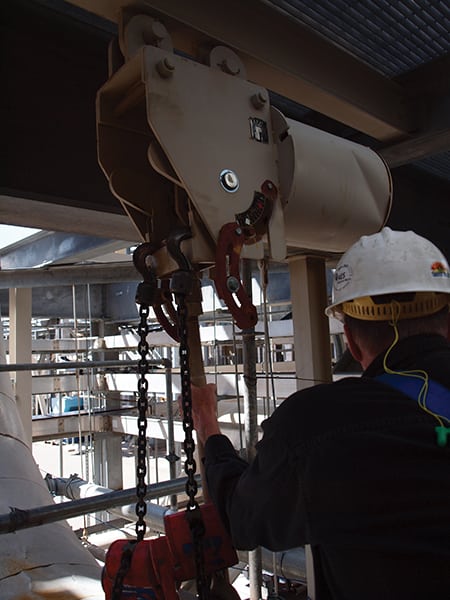
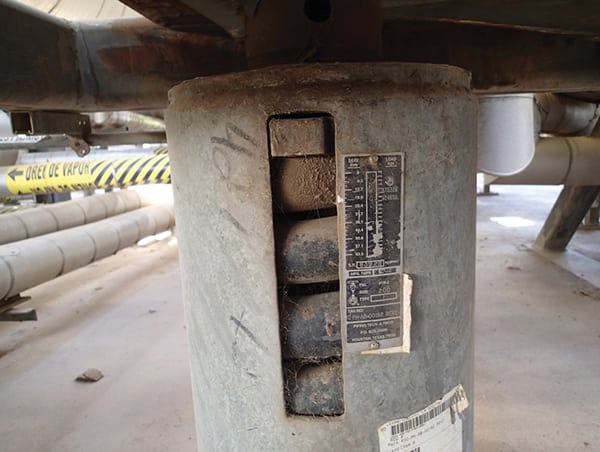
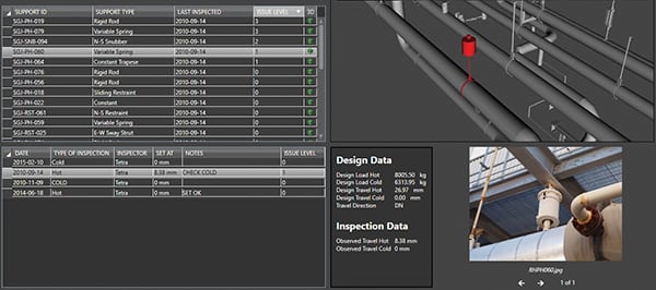
Hanger inspections evaluate the overall state of piping hangers. From visual inspection to recordkeeping, this plan determines hanger condition during operation (hot) and offline (cold). Action steps are addressed in the event a field anomaly is present (Figure 1). Repairs and alterations to hangers are not required to be performed by an “R-stamp” holder and often are performed by knowledgeable plant maintenance personnel. Hanger adjustments are made in the cold condition while the settings are confirmed in the hot condition. A record of activities is to be kept in field reports and/or in computer software (Figure 2). Field inspection intervals are to be performed by a piping engineer every three years in addition to annual walkdowns by plant personnel.
 |
|
1. Hanger support anomaly. In this image, the variable spring pipe support is topped out and needs to be adjusted. Courtesy: Tetra Engineering Group |
 |
|
2. Recordkeeping. This computer screenshot shows one way to adequately document inspection data. Courtesy: Tetra Engineering Group |
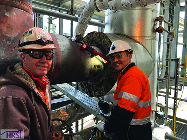
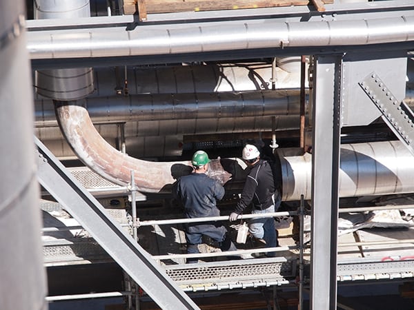
Grade 91 and creep evaluations have become an integral part of power piping scope. A great deal of industry attention has been placed on issues related to degraded and failed Grade 91 piping components at combined cycle plants (Figure 3). Special issues arise when Grade 91 steel components are welded to dissimilar materials, such as in the case of P91 to P22 or P91 to stainless steel.
 |
|
3. Nondestructive testing. The inspectors shown in this photo are looking for trouble on Grade 91 piping welds using linear phased array ultrasonic testing techniques. Courtesy: Tetra Engineering Group |
Problems also appear when the welding and heat treatment process is inadequate. In such cases, the desired microstructure is not obtained and the strength and creep-resistant properties are usually characterized as being significantly worse than P22. An efficient inspection plan should detail the procedure and specific instructions for hardness testing equipment, technique, data requirements, and reporting.
FAC inspection plans are designed to target key locations commonly affected by flow velocity, temperature, component shape, water chemistry, fluid quality, and pipe material. An effective FAC inspection plan integrates the initial audit, an assessment of all high-risk areas, a water chemistry review and consultation for reducing risk, periodic inspections for FAC-susceptible piping and equipment, and repairs of defective/deteriorated components. The time interval for these inspections is between three and five years.
FAC is commonly known to erode carbon steel components carrying single-phase water or two-phase water and steam. Normally, it does not occur in single-phase steam. The rate of wear is greatest at temperatures close to 300F, with low pH and oxygen concentrations. Geometry changes and other flow perturbations also have a significant effect.
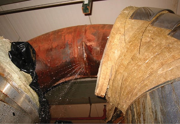
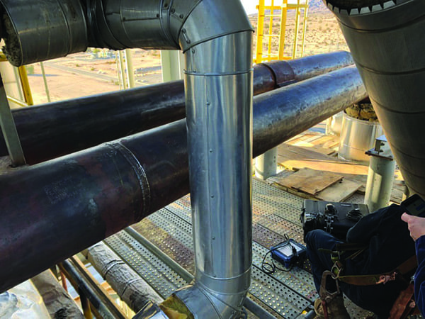
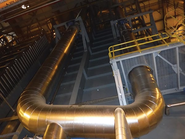
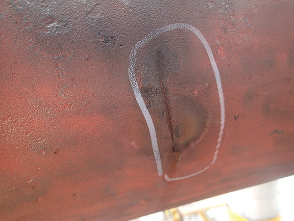
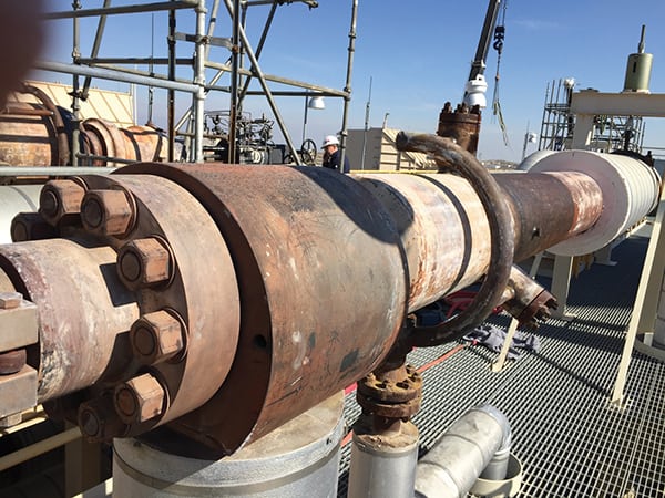
Thermal shock (Figure 4) and impingement assessments include piping that is at risk of dynamic loading, such as quench cooling. In combined cycle power plants, components at risk continue to be piping immediately downstream of the sprays, including the HP steam bypass to the CRH (Figure 5) and the HRH bypass to the condenser. Ultrasonic shear wave is one of the preferred nondestructive testing methods to detect early failures. These inspections are to be conducted every three years.
 |
|
4. Thermal shock. The failure shown here was found on a plant’s desuperheater attemperator piping. Courtesy: Tetra Engineering Group |
 |
|
5. Highly susceptible areas. It is very important to conduct inspections to identify attemperator cracking downstream of spray injection, such as in this high-pressure steam bypass to cold reheat piping. Courtesy: Tetra Engineering Group |
The B31.1 code also deals with water and steam hammer. Although these events are not frequent, they are equally important to monitor for. By definition, water hammer involves large loads that act aggressively on pipes. Any sudden change in velocity in a liquid-filled line can produce large pressure pulses, which can damage the integrity of the system. Rapid valve closing or opening is a major factor. Steam hammer occurs for similar reasons. Rapid closure of turbine stop valves can result in large loads. Accumulated condensate can be driven through steam and drain lines at high speed, producing high-impact loads when it hits pipe bends and valves. “Chapter VII Operation and Maintenance” procedures emphasize the need for recordkeeping and detailed descriptions of such events.
Implementation at CCGT Plants
If a CPS program is absent, immediate action is required. A program that monitors corrosion, creep, fatigue, and inadequate piping support systems is appropriate for all power generating facilities.
If a maintenance program is already present, only an update is needed. A comprehensive review will establish the portions that agree with the latest guidelines and the ones that lack conformance. In addition to code compliance, the incorporation process should pay attention to earlier records of failures and past recommendations. Currently, there is no rigid mold that a program has to emulate. A level of flexibility remains available to upgrade the programs as plant managers see fit.
Existing programs are allowed to combine an old set of procedures with new ones. For example, an active FAC program can work with a new CPS piping plan and risk assessment, Grade 91 inspection plan, and hanger inspection plan. Similarly, an active CPS piping plan and risk assessment and a thermal shock/impingement assessment can work with a new Grade 91 inspection plan and hanger inspection plan. There are no restrictions on how to implement an O&M program. What matters is that every aspect of Chapter VII is taken into consideration.
The sole mission of the ASME B31.1 is to promote safety. The B31.1 Code expands on the necessary guidelines for operations and maintenance. If an energy facility lacks a program, immediate action is needed. If it has one, a verification of congruence can determine the corrective actions needed to fortify the plan. Whether it is creating or reinventing an active program, code compliance is always required.
—Robert Rosario, PE (robert.rosario@tetra-eng.com) is a mechanical engineer II and (peter.jackson@tetra-eng.com) is director of field services for Tetra Engineering Group.