Combustor design simulation requires the resolution of complex geometry, turbulent flow patterns, heat transfer, and detailed chemistry. Although computational fluid dynamics (CFD) can simulate the reacting flow in realistic geometries, it requires the use of severely restricted chemistry models that are too simple to accurately simulate emissions and operational stability. A new simulation tool is now available that eliminates this CFD shortcoming while significantly reducing computing time.
Combustion turbines are uniquely capable of burning a wide variety of fuels, including very low heat content blast furnace gas, medium heat content landfill and biofuels, and higher heat content liquefied natural gas (LNG) and Fischer-Tropsch fuels. This fuel flexibility can be a headache for engineers who are responsible for designing combustion systems capable of efficiently and reliably burning these fuels while accounting for the reality that regulators continue to ratchet down permissible emission limits. To complicate the task further, each fuel has unique characteristics that impact turbine operation, such as light-off and acceleration, compatibility with dry- and ultra-low-NOx (DLN and ULN) combustion systems, combustion dynamics, and flashback.
Ask a combustion engineer how long a complete analysis of a unique fuel will take, and chances are the answer will be, "It depends." For example, diffusion flame combustors are much more forgiving of fuel changes but are limited in the possible range of NOx reduction. DLN and ULN models can meet low-NOx emission requirements but are very fuel-finicky, especially during start-up and quick load changes. Each analysis must also consider flame-blowout tendency and combustion acoustics under every conceivable operating condition.
The critical path for any thorough analysis of how a combustor will perform on a new fuel is usually a function of the quality of computer tools, the skill of the analyst, and how fast the computer can crunch numbers. A "quick" estimate based solely on the designer’s experience might be possible by tomorrow. The "best" answer may take months of running several computation computer codes to mesh the combustor and use realistic turbulence and detailed chemistry, followed by weeks of data analysis and perhaps even expensive full-scale rig testing.
Turbine manufactures can’t afford the cost and time of finding the "best" answer when dozens of unique fuel inquiries arrive every week. They also can’t bet their business on quick estimates that may prove to be inaccurate and cost millions of dollars to correct. The "right" answer lies somewhere in the middle — it balances the desires of the technical designers to field a reliable power plant and the needs of business managers, who must turn a profit with minimum risk to the corporate treasury. The "right" answer may be defined in different ways, but most will agree that a good corporate electronic knowledge base coupled with the best computational tools are two essentials for deriving a right answer.
Innovative Design Tools
Combustor design simulation requires the resolution of complex geometry, turbulent flow patterns, heat transfer, and detailed chemistry. Modern computational fluid dynamics (CFD) codes are capable of resolving complex combustor geometries and of producing complex flow and temperature fields, but they provide only limited chemistry information. Though today’s computers are fast enough to handle combustor design models with several million cells, they are still not fast enough to incorporate all of the detailed combustion chemistry of the fuel.
To save computational time, many CFD codes use severely restricted chemistry models that are too simple to accurately simulate emissions and operational stability. Others may decide to oversimplify the combustor geometry to shorten analysis time. In either case, the reduced chemistry typically used in CFD cannot represent trace pollutant species such as NOx, CO, and unburned hydrocarbons (UHC). Nor can it predict lean blow-off (LBO), which is so essential with certain fuels. The "best" analysis tools will resolve these species using detailed reaction mechanisms with hundreds of species and thousands of reactions — and do it quickly.
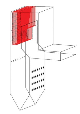
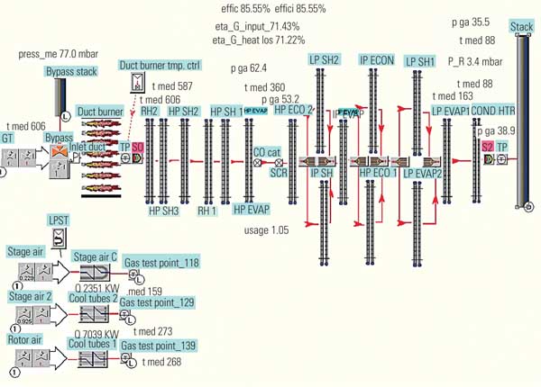
Reaction Design, located in San Diego, recently released a new set of analysis tools that bridge these CFD shortcomings while producing excellent results in a fraction of the computational time usually required. Their approach is simple in concept but conceals an enormous complexity of analysis techniques. In essence, Reaction Design’s approach treats the combustor as a series of idealized reactors so that detailed chemistry reactions are included only in regions that require the full chemistry simulation, as shown in the top half of the combustor cross section in Figure 1. Less-rigorous analytic techniques are then used in the remaining regions within the combustor, with little loss of detail. Expensive computational time is thereby optimized, yielding "best" results in a fraction of the usual time.

1. Less is more. Focusing the analytic chemistry simulation on key regions in the combustor (see top half of the combustor) saves analysis time without compromising the quality of the results. The bottom half of the combustor illustrates the equivalent reactor networks. Source: Reaction Design
Analytic Details
Reaction Design’s ENERGICO software maps idealized chemical reactors to the flow field so you can apply detailed combustion chemistry in an efficient manner to simulate trace species’ formation and destruction. The use of equivalent reactor networks (ERNs) allows the flow field of the combustor to be represented as a group of more complex, perfectly stirred reactors and less-complex plug flow reactors with associated connecting streams, as shown in the bottom half of the combustor cross section in Figure 1.
Contiguous cells are grouped into zones based on a series of user-defined filters, and then the software calculates the mass flows connecting each zone, as well as the mass flows entering each zone from external flows. For this approach to be successful, however, it is critical that the ERN is a true representation of the actual combustor flow field.
This extraordinary software tool lets the designer take advantage of full combustion reaction mechanisms without sacrificing the resolution of complex fluid dynamics. The ENERGICO simulator speeds combustion system design, allows you to use detailed chemistry without requiring specialized understanding of complex kinetics, and requires fewer, better-directed experimental tests to validate system design.
The simulation package can be used to simulate chemistry performance for any continuous-flow combustion system, using virtually any fuel. The ERN can also be employed in a parametric variation of operating conditions and fuel composition to identify how these variations affect performance.
Simplified Case Study
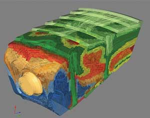
Modern CFD codes are capable of resolving complex combustor geometries and of producing complex flow and temperature fields, but they provide only limited chemistry information (Figure 2). The following much-simplified case study illustrates how the ENERGICO analysis tool overcomes these CFD deficiencies.
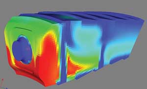
2. Incomplete analysis. This is a typical CFD solution of a gas turbine combustor
showing temperature fields. Although today’s computers are fast enough to handle combustor design models with several million cells, they are still not fast enough to incorporate all of the detailed combustion chemistry of the fuel. Source: Reaction Design
Step 1. Translate the CFD model. An analysis begins with importing the results of a CFD simulation into ENERGICO from industry-standard CFD models in CGNS format. Once ENERGICO has read the CGNS file, an automatic mapping occurs to associate species and variable names used in the CFD simulation with those that will be used by ENERGICO. The user can verify this mapping and make any corrections or additions, in case nonstandard names are used in the CFD simulation.
The user’s next step is to identify which boundaries are associated with which boundary types (for example, inlet, outlet, wall, or periodic) for each of the boundary regions found in the CFD solution. The periodicity parameters for any periodic boundaries are then defined, thus completing the model setup in ENERGICO.
Once the model setup is complete, the next step is to employ an algorithm to divide the combustor flow field into zones that will form the basis of the ERN.
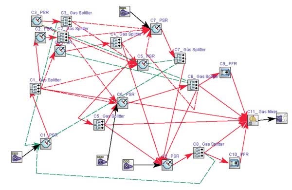
Step 2. Create an ERN from a CFD Solution. ENERGICO’s specialized software algorithms or user-customized algorithms and filter tools automatically capture the dominant flow patterns and recirculation zones from the CFD flow analysis (Figure 3). Representing the combustor with a series of idealized reactors allows the use of detailed chemistry within a reasonable amount of computational time.
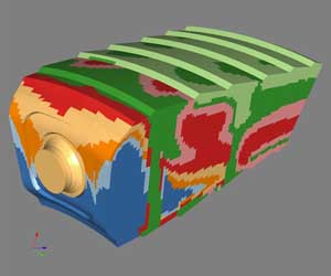
3. Network solutions. ENERGICO defines zones (see Figure 1) based on the flow field, patterns, and recirculation zones that will then be used to define an equivalent reactor network (ERN). Once the ERN is created through a careful devolution of the combustor flow field, the fully detailed chemical mechanism can be used to develop an understanding of chemical behavior and performance inside the combustor. Source: Reaction Design
The first step in creating the ERN from a CFD solution is to divide the combustor flow field into zones that will then become reactors linked together to form the ERN. ENERGICO provides two prepackaged algorithms to create zones that will be effective in providing accurate simulation of trace emissions of NOx, CO, and UHC. One algorithm looks at the gradients of oxidizer, fuel, and temperature in the flow field and divides the flow field into zones that are set to perfectly stirred reactors by default. The other algorithm refines the reactor type for each zone by setting criteria for which zones would be more effectively represented as perfectly stirred reactors and which would be better modeled as plug flow reactors. Zones that are created in the combustor flow field are viewable. Figure 4 illustrates a relatively simple five-zone reactor; an actual combustor may have hundreds of reactors.
In addition to using the prepackaged algorithms, users have the ability either to refine the algorithms for zone creation or defining reactor types, or to create and save new, user-proprietary algorithms that are targeted to more-specific types of systems.
Once the ERN is created through a careful devolution of the combustor flow field, the fully detailed chemical mechanism can be used to provide an understanding of chemical behavior and performance. For this approach to be successful, however, it is critical that the ERN is a true representation of the actual combustor flow field. The simple five-reactor representation shown in Figure 4 is typically insufficient, because modern combustor designs are much more complicated, with multiple inlet, recirculation, flame-stabilization, and after-burn regions — and potentially hundreds of reactors.
4. Zoned out. The zones shown here may also be viewed as individual reactors in an
intricate network. At this point, the ERN can either be solved using the full detailed chemistry solution for the nominal conditions, or a parameter study can set up on the RN to introduce changes for further exploration of the system design. Source: Reaction Design
Step 3. Solve the ERN. Next, select a detailed chemistry mechanism for combustion of any fuel (which may include hundreds of species and thousands of reactions) in Reaction Design’s CHEMKIN-PRO software (a prerequisite for using ENERGICO) to solve the ERN. The detailed chemistry set can be in the form of any CHEMKIN-compatible chemistry description. There is no limit on the number of species or reactions that can be included in the chemistry set. After creating the ERN with ENERGICO, the CHEMKIN-PRO software package displays the ERN and all the information regarding the individual reactors and the links between them.
Step 4. Visualize the ERN Solution on the CFD Domain. It is helpful to view the ERN solution in relation to the combustor geometry and flow field to assist in the design process. ENERGICO provides the capability to view the ERN results on each of the zones within the combustor geometry. This provides a geometrical context that will facilitate identification of modifications to the combustor design that might improve performance or reduce emissions.
Once the solution has been completed, the results for each individual reactor in the ERN can be displayed, or they can be imported back into ENERGICO for overlay display on the combustor geometry.
Figure 5 is an example of this presentation of the ERN results overlaid on the geometry, highlighting the thermal NOx formation rate in each zone of the combustor. ENERGICO provides the ability to separate the thermal NOx formation rate from the total NOx formation rate by tracking the reaction paths that lead to thermal NOx formation. Other key ERN results — such as CO, NOx, UHC, volatile organic compounds, and the soot precursor PAH — can be viewed on the combustor flow field. For convenience, NOx and CO are automatically provided in dry ppm units, as well as dry ppm corrected for 15% O2.
5. Intuitive results. Here the ERN based on the nominal conditions of the original CFD case and display results of the ERN are overlaid on the combustor geometry. Source: Reaction Design
Step 5. Conduct an LBO Analysis. Lean blow-off is one of the most challenging combustion stability problems in low-NOx combustor design. LBO occurs when the heat generated by chemical reactions is no longer sufficient to ignite the incoming fuel/air mixture to sustain the flame. In low-NOx combustor design, the low-NOx limit is often bound by the onset of combustion instability in the form of LBO. Identifying the onset of LBO is critical in combustion system design. Because this condition is dictated by real chemistry and fluid dynamics, the reduced chemistry intrinsic to most CFD tools cannot provide the necessary accuracy.
The ENERGICO simulation package uses the well-documented concept of evaluating the relative time scales for chemical reaction and fluid mixing to predict when LBO will occur. In conventional uncontrolled combustors, the combustion is limited by the degree of mixing occurring within the combustor, as chemistry is typically much faster than mixing. However, as the flame temperature is decreased to reduce NOx, the chemical reaction slows to the point where temperature becomes the rate-limiting factor and the onset of LBO may be triggered (Figure 6).
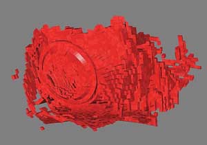
6. Lighting a match in a hurricane. To help designers determine the propensity of their system to experience lean blow-off, the ENERGICO simulation package captures the specific region in the combustor flow field that represents the flame front based on the CFD solution. An analysis is then performed, using detailed chemistry and the CFD flow field, to evaluate the viability of a flame in that location. This image shows a simulation of a lean blow-off in progress. Source: Reaction Design