Hyperbolic cooling towers remove heat from power plant condensers using natural draft. Air rises through the center of the tower, and hot water is discharged as a spray in the interior. The evaporative cooling is very effective and costs relatively little to operate.
But there’s a downside to the design. Nearly all surfaces in the tower’s basin are subject to "immersion" conditions, and the columns and lintels are in a "splash zone" environment that alternates between wet and dry. The soaking and cycling make hyperbolic towers very susceptible to corrosive deterioration. That’s hardly a good characteristic for a structure that must use as little material as possible to reduce its weight but still be strong enough to resist high winds. Loss of structural material due to corrosion is simply unacceptable.
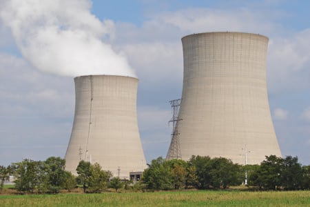
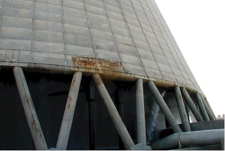
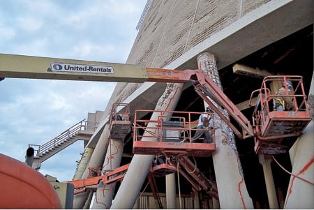
The hyperbolic tower that cools Unit 2 of the St. John’s River Power Plant in Jacksonville, Fla., is a case in point (Figure 1). Erected in 1987, the cast-in-place tower is 450 ft tall and 360 ft in diameter. Its columns and lintel beam were constructed with traditional formwork, but its veil (shell) was built using slip forms. The plant’s owners—Jacksonville Electric Authority (JEA) and Florida Power & Light Co. (FPL)—first noticed severe corrosion of the reinforcing steel bars (rebar) of the veil, perimeter columns, and lintel beam. Visual inspections noted concrete cracking, spalling, rust staining, and delamination (Figure 2).
|
1. Cool elegance. The hyperbolic tower that cools Unit 2 of the St. John’s River Power Plant in Jacksonville, Fla., is 450 feet tall and 360 feet in diameter. Courtesy: Structural Preservation Systems
|
|
2. Rust belt. In a working hyperbolic tower, practically all surfaces of its basin may endure "immersion" conditions, while its columns and lintels are alternately wetted and dried out. The swings in humidity foster corrosion and deterioration of the structures’ embedded steel. Courtesy: Structural Preservation Systems
|
Chloride, from two sources, was identified as the main cause of deterioration. The tower’s makeup, taken from the St. John’s River, is brackish water that is high in chloride content. The tower’s air supply only exacerbates the problem. Coming from the nearby Atlantic Ocean, the salty air increases the chloride levels at the columns and lintel beam. Once the brackish water and salty air start the corrosion process, the reinforcing steel begins to rust and expand. The cracks that form in the concrete admit more chloride and oxygen, creating a vicious circle.
No time to lose
Because corrosion-induced deterioration is a progressive condition, it was essential for the plant’s owners to get a handle on the causes, consequences, and scope of the problem as quickly as possible. The first step was to hire a specialist to perform a detailed visual and hands-on inspection of the lower 50 ft of the tower (limited access precluded going higher). The contractor did the following:
- Measured and documented structural geometry, deflections, displacements, cracks and other damage.
- Extracted samples at various depths and measured their chloride content.
- Mapped the electrical potential and continuity of the entire lower section of the tower.
- Used a pachometer to determine the location, depth, and size of the structure’s reinforcing bars.
The nondestructive testing (which was conducted in accordance with concrete industry standards) confirmed that the lintel beam and columns were in poor condition, with heavy cracking and spalling. Separately, testing of the samples revealed chloride levels above 2.2 pounds per cubic yard at all measured depths. Together, the two tests verified that ongoing corrosion of rebar was the cause of the structural deterioration.
Eliminating the cause
Repairing corrosion-induced deterioration typically requires removing the weakened concrete, cutting it to expose its rebar, cleaning the rebar, and then recreating the original concrete section. At St. John’s River, this would have fixed the damage, but not the underlying problem.
To end corrosion-induced deterioration once and for all, the plant’s owners decided to not only repair the lintel beam and affected columns but also to "jacket" them with a cathodic protection system. A cathodic protection system (see box) for a steel-reinforced cooling tower consists of encapsulating zinc mesh anodes within a stay-in-place fiberglass form filled with cementitious grout. The zinc mesh, which is welded to the rebar, provides protection for the rebar and its surrounding concrete by serving as a "sink" for corrosion. Such systems have proven easy to install, maintenance-free, and cost-effective in a wide range of applications.
The plant’s owners chose Structural 
Preservation Systems Inc. (SPS), a leading specialty concrete repair contractor, to repair the tower and install the cathodic protection system. The company (www.structural.net) has a solid track record on projects similar in type and size. The project at the St. John’s River plant began with preplanning activities and a site visit by SPS. It took more than a week for plant staff and SPS specialists, acting as a team, to determine responsibilities, schedules, and logistics, and to design the jacket-lifting system and temporary formwork needed to complete the job. Next, satellite images of the site were used to identify lay-down and staging areas and the location of temporary facilities. This planning step was extremely important because many subcontractors would be working in close quarters.
The project called for the installation of 120 lintel beam jackets and 240 column jackets for a total of 34,000 square feet of fiberglass jacketing. But before the jackets could be placed and grouted, the deteriorated concrete had to be repaired. This would require the removal of delaminated concrete by pneumatic chipping guns, the profiling of concrete surfaces, and the cleaning of corroded rebar by 35,000-psi water blasting equipment and pneumatic handguns.
Safety first
Although the hyperbolic tower was designed to withstand 110-mph winds, the team decided to reevaluate its stability to confirm that the repairs wouldn’t undermine it. To do that, Existing Structures Engineering 
Inc. entered the tower’s total weight and the static pressure on each column into the structural engineering program STAAD.Pro 2004, from Research Engineers International, a division of netGuru Inc. (www.reel.co.uk). The software can generate a model based on static, dynamic, p-delta, and nonlinear analyses.
The tower was first modeled assuming its original design criterion of a 110-mph wind load and then in a demolished state, with a 72-mph load (Figure 3). Based on these two simulations and calculations done by hand, it was determined that concrete could be safely removed from all lintel sections and 40 of the 80 columns of the tower at the same time. The results also indicated that the lintel and columns could be stripped of 3 inches of concrete on all faces (Figure 4).
|
3. Super model. A structural engineering program virtually recreated the tower using data from design documents and inspections and the results of nondestructive testing. The application indicated that, even if a storm with 72-mph winds were to arrive, it would be safe to strip or demolish the concrete and repair the lintel sections of 40 of the tower’s 80 columns simultaneously. Source: Structural Preservation Systems
|
|
4. Undoing the damage. Deteriorated concrete and rebar had to be repaired or restored before the cathodic protection system could be installed. Pneumatic chipping guns were used to remove delaminated concrete, while 35,000-psi water blasters and pneumatic handguns cleaned the rebar. Courtesy: Structural Preservation Systems
|
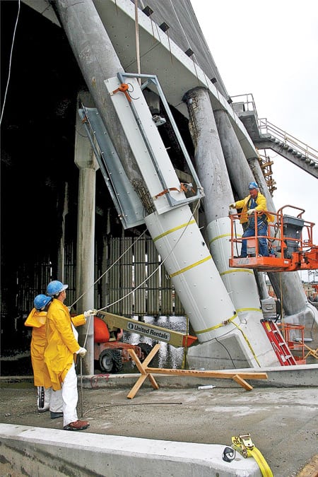
Because the lintel jackets had an odd shape, lifting them into position and supporting them while they were grouted wouldn’t be easy (Figure 5). SPS considered several methods and ruled out all but one as too cumbersome and time-consuming to meet the project timeline. The method chosen involved building a grillage to temporarily hold the jackets in place and fasten them to the lintels until the grout cured.
|
5. Extra-large jacket. Some 120 lintel beam jackets and 240 column jackets with a total area of 34,000 square feet were installed. Courtesy: Structural Preservation Systems
|
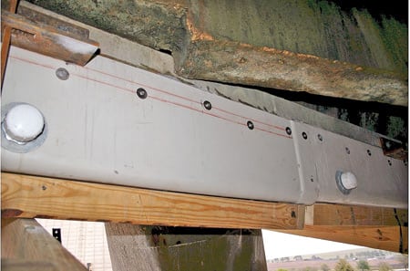
The plan was to suspend the grillage formwork by using steel rods and structural steel brackets to mount it to the interior and exterior of the tower. First, however, the grillage had to be prepared to accept the stainless steel fasteners that would hold the jackets in place (Figure 6). Because the final placement of the fasteners was important for aesthetic reasons, holes for them had to be drilled at precise locations. Using an aerial lift, the jackets were attached to the lintel beam. Then, cementitious grout was pumped through ports on their back face at 4,000 psi.
|
6. Not going anywhere. The jackets were attached to the lintel beam by pumping cementitious grout at 4,000 psi through ports on their back face. Courtesy: Structural Preservation Systems
|
Attaching the jackets to the columns was equally challenging because of the compound angle of the columns. To simplify the task, SPS designed and fabricated a lifting bracket (Figure 7) that, once off the ground, was at the correct angle to slide the jacket into place.
|
7. Facilitated fastening. For each column, the jacket was divided into six pieces—two each for the bottom, middle, and top. Each section was lap-spliced and held in place with stainless steel fasteners. Brackets held up the jackets through the grout portholes, while the jackets were held open by straps attached to the lifting bracket. Courtesy: Structural Preservation Systems
|
For each column, the jacket was divided into six pieces—two each for the bottom, middle, and top. Placement started at the bottom with two pieces resting on the foundation and subsequent pieces supported by the ones below. Each section of the jacket was lap-spliced and held in place with stainless steel fasteners. Brackets held up the jackets through the grout portholes, and the jackets were held open by straps attached to the lifting bracket. Once the jacket was around the column, the strap was released. Next, ratchet straps were wrapped around each section of jacket to increase its hoop strength and to keep it from warping during grouting. Grouting was again done through ports in the jackets, but these were at 2.5-foot vertical intervals and alternately placed on the faces of the column (Figure 8).
|
8. Belt and suspenders. Once the jacket was around the column, the strap was released. Then, ratchet straps were wrapped around each section of jacket to increase its hoop strength and to keep it from warping during grouting. Courtesy: Structural Preservation Systems
|
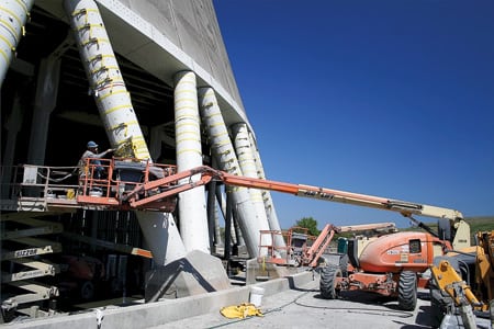
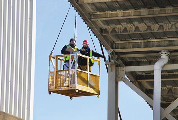
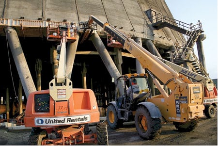
Gaining access to the repair areas was even more challenging. Nearly all of the work on this project was done using aerial lifts—16 articulating and two of the 4 x 4 scissor type. Because this procedure was new to most of the crew, SPS arranged for instructors to come to the job site and provide field and classroom training. The sessions, which emphasized safety and the need for communications, gave the crews the opportunity to practice operating the lifts in close quarters and taught them what needed to be checked before activating them.
Burning the midnight oil
The repair and installation work was scheduled for a five-week period during a planned outage of Unit 2. But an unforeseen eight-day delay for a chemical cleaning of the tower’s internal fill made the schedule even tighter. To make up the time, SPS asked for and received plant management’s approval to move to a 24/7 work week.
The fact that three other contractors were working on the tower during the same period only complicated the logistics. One was working inside the structure cleaning and replacing some of the fill, using Bobcats and other machinery below the SPS work area. The other two contractors were working on the veil of the tower; one was doing hydro-demolition and the other was applying zinc mesh and shotcrete to an overlay above the SPS work. Both were using multiple 120-to-150-foot aerial lifts that required constant vigilance to avoid a mishap.
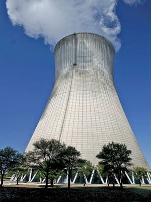
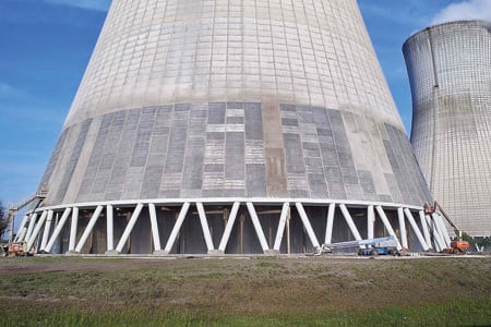
The three Cs made the busy and crowded project a success: cooperation between contractors, coordination, and communication. The result was as beautiful as the shape of the restored (and now corrosion-protected) tower (Figure 9): a perfect safety record for the 35 men who logged 16,000 man-hours on this job.
|
9. Beautiful ending. Years of experience working on tight schedules during plant outages made the St. John’s River project a success. It was the largest cathodic protection system that SPS has ever installed. Courtesy: Structural Preservation Systems
|
—Kraig Tarou is division manager for Structural Preservation Systems LLC. He can be reached at ktarou@structural.net. Stan Boshart is a project engineer at the company; he can be reached at sboshart@structural.net.