If engineered well and drained properly, a simple finned-tube heat exchanger can help maximize a fossil-fueled power plant’s combustion efficiency, capacity, and air pollution reduction. Use the guidelines in this article either to return a disabled steam coil air preheater to service or to improve the performance of a unit that may have been wasting steam and money for years.
Steam coil air preheaters (SCAPs) are found in most fossil-fueled utility and large industrial power plants in North America. Their primary function is to heat combustion air before it enters a rotary regenerative air heater (POWER, April 2006, p. 72) or a traditional tubular air heater. Whether a rotary regenerative air heater (RRAH) or a traditional tubular heater is downstream, the SCAP provides corrosion protection for the heater and maintains its cold end average exit gas temperature above a minimum. Improvements in boiler efficiency and heat rate and in unit capacity from heating of combustion air have been documented for decades.
Smaller industrial boilers fired by hog fuel or used for chemical recovery may use a SCAP as the primary preheater of combustion air. Increased use of alternative fuel sources such as hog fuel, biomass, tire-derived fuels, and refuse-derived fuels have made it more important to optimize the use of SCAPs.
Stricter emissions standards also have changed the utilization of SCAPs. With plants’ increased use of selective catalytic and noncatalytic reduction (SCR and SNCR) systems and other emissions-reduction equipment, SCAPs now are needed year-round—rather than just during the ozone season—to maintain heaters’ outlet gas temperature.
Location, location, location
|
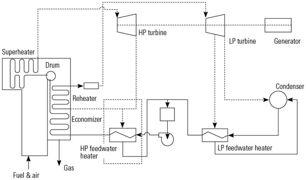
1. Simple in concept, complex in operation. A rough schematic of a typical steam coil air preheater. For simplicity’s sake, the system shown depicts single coils in walls and ducts. In an actual system, the steam supply and condensate return lines typically feed 6 to 40 coils per forced-draft fan. Source: Armstrong Heat Transfer Group
|
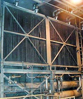
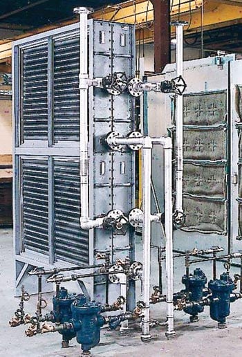
Figure 1 is a very simplified schematic of a SCAP. Most units use vertical finned-tube coils embedded in perimeter entry walls to connect to the suction side of a forced-draft (FD) fan or fan room —the source of combustion air. Some SCAPs, however, are designed to be installed on the discharge side of the FD fan, between the fan’s ductwork/transitions and the duct connection to the inlet (cold end) of an RRAH. As opposed to being bolted in place by duct flanges (Figure 2), units used in such a configuration are usually drawer-mounted, for easier access and removal (Figure 3).
|
2. Bolted in place. A wall-mounted steam coil air preheater with common receiver drainage. Courtesy: Armstrong Heat Transfer Group
|
|
3. Easier to replace and maintain. A pre-piped, duct-mounted, drawer-type steam coil air preheater with individual coil trapping. Courtesy: Armstrong Heat Transfer Group
|
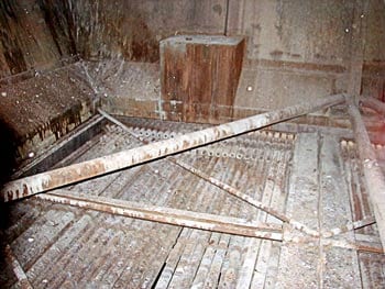
Placing a SCAP ahead of the cold end (inlet side) of a RRAH, however, can invite maintenance problems and shorten unit life. For example, if a SCAP is placed directly below an RRAH, corrosive sediment and crud dislodged during basket washdown will fall onto coil-finned surfaces and accumulate there (Figure 4). Clogging and reduced performance will be the undesirable outcome. Often (but unintentionally), the SCAP’s coils serve as a convenient platform for maintenance workers tasked with cleaning and inspecting the RRAH.
|
4. Look out below. Because this steam coil air preheater (SCAP) was mounted directly below a rotary regenerative air heater, corrosive sediment and crud dislodged during RRAH basket washdown fell onto the SCAP’s finned-coil surfaces, damaging them. Courtesy: Armstrong Heat Transfer Group
|
Another undesirable consequence of placing a poorly constructed, specified, or drained SCAP just upstream of the cold side of an RRAH is the development of steam and/or condensate leaks in the air stream. This can lead to evaporative cooling of the RRAH’s surface, which “steals” valuable energy from the unit. All three of these SCAP-related problems—increased maintenance requirements, shortened life, and higher-than-necessary energy consumption—have been reported by large fossil fuel–fired power plants in the U.S. and Canada.
Problem children
Utility boilers obviously can and do remain functional without the help of a SCAP. However, the lack of a SCAP may reduce a boiler’s combustion efficiency enough to make its unit only marginally profitable. Minimizing a unit’s heat rate and maximizing its capacity requires creative modifications of the entire SCAP “loop”—comprising all components and controls from the steam source to the condensate return.
It’s surprising that so many power plants have had so many problems with SCAPs; after all, they are fairly basic finned-tube units for exchanging heat between steam and air. EPRI has documented that, since the 1980s, many SCAPs have been shut down, removed, or partially blanked out of service due to maintenance, repair, and/or performance-related (leakage) issues early in their operating life. Often, problems appeared within only a few years of plant start-up and commissioning.
At the other extreme, SCAP coils at some plants have been on the job for up to two decades, but they may have been performing well below design parameters and wasting steam for years. Often, such inefficiencies and losses go undetected, either due to cutbacks in maintenance budgets or because other maintenance items are considered a higher priority.
A recent cursory inspection by the author’s company of just a few U.S. fossil fuel–fired utility plants revealed that hundreds of SCAP coils had been isolated because they failed prematurely or required excessive maintenance. A similar trend has been noted across the U.S. and Canada, regardless of fuel type or plant location. As maintenance budgets and staffs have shrunk, SCAPs have fallen into the category of “troublesome” equipment not worth keeping in service. Accordingly, they often receive little or no attention during outage planning for design upgrade or correction.
Where and why SCAPs go bad
Among the common system causes of steam coil air preheater problems are the following.
Desuperheater stations. Because they provide pressure let-down and steam temperature control of a SCAP system, desuperheater stations must be operated accurately and continuously. At a minimum, failing to regulate the quality and amount of desuperheating water and associated feedback systems drastically reduces SCAP performance. At worst, failing to desuperheat steam for optimum SCAP condensing requirements stresses the unit’s coil materials at key weld joints, with catastrophic consequences. Among them is the passing of live, uncondensed steam to the condensate system, overheating it. Desuperheating to a level of no more than 100 degrees F above saturation temperature is a good guideline for SCAP design.
Scheduled maintenance of desuperheater station components does more than just improve SCAP performance. The attention indirectly helps improve critical pressure differentials across the SCAP system, improving drainage. One large Midwest power plant experienced measurable reductions in wasted steam flow through targeted maintenance of desuperheater stations during scheduled outages.
Coil issues. A SCAP that underperforms or fails prematurely may be a “victim of circumstances.” Possibilities include airside fouling, damage during handling or removal, dirty finned tubes, changes in steam conditions, and poor positioning of the SCAP relative to the air heater it serves.
Condensate drainage and noncondensables venting issues. Poor drainage and venting practices retard efficient heat transfer in SCAP tubes. These problems can easily be remedied either by improving the design and specifications of materials, reestablishing original steam conditions, or following industry best practices for venting, draining, and maintaining auxiliary components (more on these later).
Original design issues/reviewing changes to existing installations. Through discussions among a plant’s engineering staff, a consultant, and a qualified representative of the equipment vendor, contracts for upgrading a SCAP can be integrated with planned unit modifications. The resulting overall improvement in plant heat balance helps ensure that all aspects and components of the SCAP are viewed holistically.
Every SCAP system design should include not just the coils, but also options for condensate return and steam conditioning and control, provisions for steam trapping and venting, and—potentially—the use of flash recovery (see below). Valuable extraction-sourced steam can be saved by a thorough system overview from extraction point to condenser supply point. Often, a modest investment funded by the plant’s O&M budget can result in notable improvements. Justifying modifications of a SCAP system on the basis of the plant environmental performance gains they would produce is a common and acceptable practice.
Solving SCAP problems
A total systems assessment—including supply and drainage piping design and operational control details—is recommended as a first step. A project that is limited to coil replacement has little chance of eliminating most common SCAP problems.
The steam-source review portion of the systems assessment should include the following three steps:
1. Confirm the steam source conditions and setpoint criteria. Usually, the source is superheated steam extracted from the turbine. But often, for cold start-ups, the steam source is an auxiliary or start-up boiler. Because the type of unit service (baseloaded or cycling) affects SCAP utilization, large variations in the pressure of the steam supplied to a SCAP may affect its performance, drainage, and life. If the characteristics of the steam source have changed significantly since the SCAP was designed and placed in service, an overall system modification may be in order.
2. Evaluate the desuperheating stations. Are they working at the proper flow rates and with properly treated water supply? Are the controls operating properly? Are gauges and transmitters calibrated and reporting accurate data to the control room?
3. Evaluate the superheated steam supply and the trapping ability of the pressure-reduction station. Because failed traps and blow-through cause unnecessary energy losses and operational problems, it’s a good idea to test traps regularly—at least once a year. At that time, all piping insulation should be inspected to ensure that it is in good condition.
Options for modifying steam supply
Consider slightly increasing the steam pressure to the SCAP (after consulting its manufacturer). Doing so may allow fin spacing to be widened, possibly reducing the number of rows needed, airside pressure drops, and airside fouling of the finned coils.
In the case of fouling of wall-type SCAPs, realize that the finned surface in the first/face row of a SCAP acts as a filter. Unless fin spacing is widened sufficiently (for example, from 11 to 12 fins per inch down to 7 to 8 fins per inch, to allow particulate matter to “pass through”), nearly all coil first-row surfaces will eventually foul. Pressure-washing these surfaces at least once a year (when the coils are off-line and cool) is highly recommended.
However, widening the fin spacing on replacement coils will reduce the heat transfer surface and the temperature of the air leaving the coil (at the same steam pressure). As a result, it will be necessary to slightly modify steam supply pressure following any desired change in fin spacing. But efficiency improvements—including a smaller reduction in desuperheating pressure and a reduction in fouling and airside pressure drop (which shows up as a saving in horsepower of the FD fan)—will result.
Construction, drainage, and venting
Follow industry minimum best practices for unit design. Insist on compliance with ASME Section VIII, Division 1, as code/inspection criteria. SCAPs my not necessarily require the “U” stamp, but the added assurances of an inspector’s review and tight supplier quality control/quality assurance procedures can add longevity in the key areas of welding procedures and materials selection. (See box for a list of SCAP construction recommendations, delineated by component.)
Bear in mind that units intended for use as nonsteam, air-cooled condensate/fluid coolers may not meet construction standards for SCAPs. Although such units meet other industry standards (such as API-661 for rolled tube/header joints, box headers, and the like), these designs may unnecessarily raise costs and confuse materials/construction criteria. One way to minimize SCAP maintenance and repair costs is to use drawer-type units, where possible, to facilitate coil removal, replacement, and inspection. Maintaining spare coils for these designs allows for quick change-outs and off-line repairs, minimizing downtime.
If a SCAP’s drainage and venting systems are not designed and maintained properly, valuable heat in the steam designed for release in the unit may pass through it into the condensate system. This would rob the turbine of energy, increase the generating unit’s heat rate, and reduce its output. Steam trap selection is important. Typically, using carbon or forged-steel inverted buckets and/or floats and thermostatic steam traps that are sized for a SCAP’s minimum and maximum operating pressures and flows extends the life of the unit’s coils. Slow-cycling or thermostatic trapping devices should never be utilized on SCAP coils. For example, a Midwest utility recently reported earlier failures of coils that incorporate thermostatic traps compared with those in which inverted buckets originally were installed.
Traps should be mounted as close to (but always below) coils as possible without reducing the size of outlet piping. The traps’ discharge level should always be below the lowest outlet coil level. Use “tees” and “crosses” rather than elbows and reducers. Properly sized strainers should be installed ahead of steam traps with valved blowdown connections and should be tested annually for clear flow and proper operation.
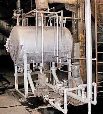
SCAP coils often are designed without traps. In such cases, as many as 30 to 40 individual coils are drained to a common receiver/accumulator (Figure 5) with liquid seal level control. This practice—called “master trapping”—requires that airflow over the entire face of the SCAP be absolutely uniform. However, because uniform airflow over the finned surfaces is highly unlikely, the condensing rate on the coil faces probably will vary. Among the factors affecting airflow uniformity are fouling of the unit’s air-side surfaces, the geometry of the air inlet side duct, and even the location of the forced-draft fan relative to the coils.
|
5. Uniform airflow required. A typical “master trapped” steam coil air preheater condensate collection system. Courtesy: Armstrong Heat Transfer Group
|
Individual trapping of coils offsets the negative effects of poor airflow uniformity. Facilities with properly sized, piped, and maintained trapping systems typically suffer fewer coil problems—because by design they enable full utilization of the supplied steam by the coil and prevent steam from passing through to downstream piping/drainage systems.
A continuous venting device installed on the receiver will ensure the release of gases such as O2, CO2, and N2 that reduce heat transfer. Ideally, each coil or coil bank should be equipped with an automatic air venting device to preclude variations in the condensing rate across sections. Venting only at start-up is insufficient. Often, this practice allows the system to fill with noncondensables that plate heat transfer surfaces, reduce efficiency, and lead to long-term fluid-side corrosion issues.
If a common receiver is used, ensure that its level control is adjusted and operating properly to prevent condensate from blowing through to downstream accumulators or the condenser. If blowthrough occurs, more energy literally goes “down the drain” than does work inside the SCAP. Condensate overtemperature alarms may indicate a control problem, such as steam blowing through coils to the return system or the failure of a header drip trap that drains to the common accumulator.
Finally, ensure that the pump used to remove condensate from the accumulator has enough head to handle high-temperature condensate and that its controls are functioning properly. A steam-powered, pneumatic, or mechanical pump may be more suitable than a centrifugal pump for this application.
Flash steam recovery
The electric power industry is warming to a concept for maximizing SCAP utilization that has proven itself in the food-processing and chemical manufacturing sectors for years. The idea is to exploit the tremendous potential energy in the volumes of steam generated by hot condensate by “flashing” the steam to a lower pressure (for example, reducing 100-psig condensate to 15 psig and using it in a backpressure system).
Several utility plants now are considering SCAP flash volumes in additional, low-pressure air preheater “booster” coils. Other ideas include reducing parasitic load extraction for better support of “auxiliaries” such as HVAC systems, hot water heating loops, showers, and low- and medium-pressure docks and door heaters. The direct paybacks of these approaches are gains in unit capacity and improvements in turbine-generator heat rate. The indirect benefit is to offset the environmental impact of generation needed to drive the loads represented by these “necessary” parasitic requirements. Using flash steam also lowers the temperature of condensate, increasing the efficiency of the condenser and further lowering overall cycle heat rate.
Closing the loop
A thorough assessment of the entire SCAP loop (from steam supply, through return, to the condenser and feedwater heater) is highly recommended. At many power plants, such a comprehensive, in-depth evaluation has led to measurable improvements in boiler heat rate, recovery of “lost” kilowatts, extension of SCAP longevity, and reduced pollutant emissions.
If a steam coil air preheater system is designed properly, its renewed use also will provide measurable and acceptable returns on investments in maintaining it. The SCAP, an often-forgotten but nonetheless key plant auxiliary system, could be reborn as a major contributor to efficient fossil-fueled power generation.