The alchemy of burning any solid fuel-including coal-requires mixing fuel and air in just the right proportion at just the right time. Get the recipe wrong, and reduced efficiency and load rating will push your unit’s production costs through the roof. Suboptimal fuel/air ratios also make combustors more likely to produce excessive levels of pollutants.
Inaccurate measurements that underestimate actual levels of primary air (PA) flow in a coal plant are particularly problematic, because higher-than-expected PA flow levels wreak havoc on more than just combustion efficiency and maximum unit capacity. Excessive PA levels also increase auxiliary loads and the operating costs of emissions-control systems; they may even make coal mills and pulverizers more prone to explosions. Because the causes and consequences of high PA flow (see box) are reasonably well understood, it is likely that your plant’s general maintenance practices already address them. But it never hurts to review the details.
Wrong numbers
A number of calibration and PA flow testing irregularities were discovered after the commissioning of a 700-MW (nominal) coal-fired unit in a Midwest state a few years ago. Following the unit’s first start-up, many of its key operating specs were not met. Targeted, ad hoc measurements revealed that PA flow was actually 25% higher than the plant’s set of flow indicators was reading. Over time, it became clear that the higher-than-expected PA levels had several root causes.
One causative phenomenon was completely unexpected because it was occurring in the unit’s coal mills and pulverizers. Whenever coal dust spontaneously combusts-either as a puff or a small explosion-the force "rounds out" a mill’s rectangular primary inlet air ducts ever so slightly. Over time, the cumulative effect is to increase the area around the flow-measuring pitot tubes in the ducts. The increased flow area in each duct changes the relationship between PA flow and pitot tube differential; consequently, greater airflows and velocities are needed to produce the same velocity pressure.
The end result is increased PA flow at the same coal flow. The PA flow control system maintains the increased level because it seeks to maintain the same duct flow signal. The problem with that, however, is that the control system continues to operate as it was calibrated, prior to any impact of puffs or explosions on duct flow area.
To understand why this happens and is a serious problem, take a look at Figure 1, which shows the inputs and outputs of a typical PA flow control system for a pulverized coal-fired unit. The pitot tube differential signal (ΔPPITOT) piped to the mill’s primary airflow transmitter ultimately relays a flow-proportional signal (via the square root extractor) to the flow control system. The comparator receives this measured duct airflow signal and compares it to a setpoint airflow signal generated by the mill’s measured feeder coal flow (using a curve that correlates the coal flow with a primary airflow). The comparator then converts the difference between the duct airflow and the coal feeder flow setpoint to an actuating signal that opens or closes the PA flow control damper by the correct amount. As the PA flow then changes to more closely conform to the setpoint flow, the pitot tube differential changes accordingly, initiating a new cycle of flow control.
1. Managing air. The design of a typical system for controlling primary airflow to and from coal pulverizers. Source: Botts Engineering Services Inc.
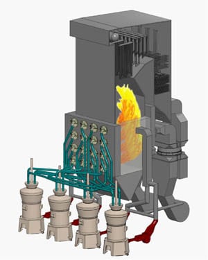
Even worse, PA flow control systems that were calibrated prior to mill puffs and/or explosions could propagate deviations between measured and actual levels and further elevate PA flow. In such cases, subsequent mill start-ups will run at leaner air/coal ratios and higher air velocities, increasing the probability of mill puffs and explosions. Unless accurate and updated calibrations are loaded into the control system, a deleterious regenerative feedback loop will be set up. More incidents of mill puffs and/or explosions will occur, further increasing duct flow area and fostering even more puffs and explosions, ad infinitum (actually, until duct failure). Figure 2 shows the test locations where traverses were conducted at the PA inlet duct to the mill and at the coal piping of the Midwest plant.
2. Testing challenges. A primary airflow testing arrangement. Source: Botts Engineering Services Inc.
Modifying ducts or adding dams to reduce the flow areas around the pitot tubes would still require recalibration of the PA flow control system-but to avoid the opposite effect. Making the flow areas smaller would increase velocity pressures at the same airflow, and as a result the PA flow control system might provide inadequate flows for drying coal within the mill and/or blowing stagnant coal out of horizontal conduits (coal layout).
Clean air act
The only way to ensure that a PA flow control system is calibrated correctly is to perform clean air testing procedures. Conducting tests only at the coal piping (even at traverse-plane locations far enough upstream and downstream of flow disturbances) invites the introduction of inaccurate calibration data. Why? Flows measured at the coal piping are affected by seal airflows introduced through the coal feeder and pulverizer and/or air leakage from the pulverizer and feeder housings, coal valves, or down spouts.
The flows introduced or lost between the points where the pitot tubes "see" the duct flows (that provide a given velocity pressure) and where flows are measured in the coal piping produce calibration data that will not make ΔPPITOT proportional to the square root of the flow. Because the PA flow control system assumes this relation, instrument flows calibrated from coal piping flows alone can deviate appreciably from actual flows, depending on the magnitude of seal airflows or leakages. At low pitot tube differentials, the seal air adds significantly to the lower coal pipe flows (Figure 3), but its influence diminishes at greater pitot tube differentials (higher test flows).

3. Leaks lessen output. This chart illustrates seal air effects on coal piping flows. Source: Botts Engineering Services Inc.
The net effects of leakage flows from, and seal airflow into, mills and pulverizers can be significant (see the "Total coal pipe flows-seal air on" column of Table 1). The flow factors listed in Table 2 show that the leakages were two to three times greater than the seal airflows, resulting in the "seal air on" flows being closer to the "seal air off’ coal pipe flows than to the inlet duct flows. Inlet duct flows shown in Table 1 are area-compensated to correct for the expanded ducts’ greater flow areas, as previously discussed. Mill puffs and explosions had occurred (as the expanded duct flow areas in the tables make clear) and had variable effects on each pulverizer’s pitot tube differential-to-inlet duct flow relation.
Table 1. Pulverizer inlet/outlet airflow comparisons Source: Botts Engineering Services Inc.
Two caveats
Two things to keep in mind when deriving PA flow calibrations: Clean air tests are conducted when pulverizers are cooler than during normal operation; and there is no coal within the pulverizers to reduce air leakage through feeders, coal valves, and downspouts. Seal air gaps also will decrease and close more tightly as metal temperatures increase from start-up to operation. This condition can be confirmed if the amount of hot air leakage detected at the base of operating pulverizers is negligible.
Considering these conditions allows operational flows to be correlated more closely with inlet duct flows-especially at mill full load, where seal airflow has less effect on coal piping flows. In fact, using the "seal air off" coal piping flow numbers in Table 2 would lead to a very inaccurate calibration: Actual PA flows would be up to 1.23 times higher than the reading of the flow instrument transmitted to the pulverizer and boiler controls. Furthermore, calibrations derived from a coal piping test would not adequately address the original high PA flow condition and would continue to exacerbate the problem.

Table 2. Pulverizer inlet/outlet airflow factors Source: Botts Engineering Services Inc.
Clearing the air
A later uprate study (Table 3) for our Midwest plant illustrates the combined effects of:
- Six-mill operation (with the mill feeding the front wall upper burner row out of service) compared to operation with all seven mills.
- Calibrating four of the six operating pulverizers with the new, "initial" PA flow data.

Table 3. Unit operation before and after initial primary airflow calibrations Source: Botts Engineering Services Inc.
The study’s primary goal was to uprate the unit’s capacity to at least 700 MW (gross), with one pulverizer out of service, to match the capacity of a sister unit. The study found that the coal feeder flows were too low to provide the required heat release for generation of 700 MW and that the PA flows were high and out of calibration (based on the clean air test flows). These "initial" PA flow calibrations were based on the original pulverizer inlet duct flow area. Later, "more accurate" PA flow calibrations were developed and used after discovering the extent of the expansion of duct flow areas listed in Table 1.
The reduction of PA fan power consumption (indicated by the lower amperage figures after loading the "initial" calibrations) was a direct result of the lower PA flows discharged to the boiler. The effects of air heater leakage on induced-draft fan power consumption were assumed to have remained constant, because the unit was in continuous operation before and after recalibrating the four mills’ coal and PA flows.
The reduction in PA flows decreased flyash loss-on-ignition (LOI) values (Figure 4). The "initial" PA flow calibrations were loaded into the control system of the four mills’ controls prior to July 3. The "more accurate" PA flow calibrations were loaded beginning July 6 and completed on all pulverizers by July 13.
4. Leaks also lower LOI. Drops in loss-on-ignition followed reduction of primary airflow levels. Source: Botts Engineering Services Inc.
Secondary airflow calibrations then were increased for all pulverizers (on July 6 and 7) to provide sufficient combustion airflows for the higher feeder coal flow settings. The original secondary airflow control settings for the four recalibrated pulverizers were too low for these higher feeder coal flows. The secondary airflow increase showed no measurable influence on subsequent LOI values in the days that followed, with LOI rising to previous levels. The direct effect of the more-accurate PA flow calibrations appeared on July 13, when flyash LOI dropped to 0.20%. The LOI excursions on July 28 and August 17 still have not been explained, but on July 24 the unit began operating at 680 MW with six mills in service.