Combined cycle power plants use fuels and other materials that can cause fires or explosions in the combustion turbine, ducting, or heat recovery steam generator. Purging that equipment with ambient air to displace residual combustible gases before starting is a normal safety practice. But when plants are cycled, the disadvantages of purging often outweigh the advantages.
Explosions and fires in a combined cycle (CC) plant may be rare, but when one occurs, it normally results in an extended outage for repairs. One cause of these undesirable events is the accumulation of vapors and liquids in the combustion turbine (CT) and heat recovery steam generator (HRSG) system during a shutdown that can combust during unit startup. In the U.S., this potential is addressed in National Fire Protection Association (NFPA) 85: Boiler and Combustion Systems Hazards Code (2011). The code sets “design, installation, operation, maintenance, and training” standards for “safe equipment operation” for all but the smallest fired and unfired steam generators.
NFPA 85 for many years has required a fresh air purge of the CT, HRSG, and other CT exhaust systems (for example, by bypass stack) prior to CT startup and operation. The purge rate is a mass flow requirement to provide the required air velocity to ensure dilution and removal of combustible gases prior to light-off of the CT. This purge is specified to be at least five volume changes and no less than 5 minutes in duration. Typical purge times range from 5 to 18 minutes, depending upon the fuel selected, HRSG and duct design, and guidance from the original equipment manufacturer (OEM). The purge cannot be less than 8% of the full power mass flow of the CT.
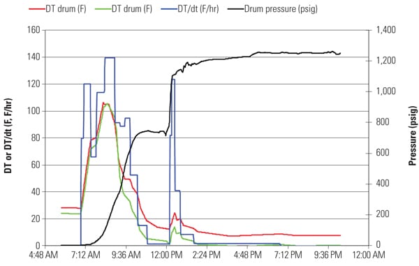
The requirement to purge equipment, from the CT to the exhaust stack, may protect the CC system from the hazards of fire and explosion, but complying with the code also imposes performance and reliability challenges. In CC plants, steam-side startup is typically determined by the temperature of key steam generation systems, which then controls the steam turbine ramp rate up to operating conditions (Figure 1). The exact values vary from plant to plant, but typical numbers are:
- Cold starts: No pressure on steam system, prior shutdown greater than 24 to 30 hours.
- Warm starts: High-pressure steam pressure is typically 60 to 200 psi, after a shutdown of 10 to 20 hours.
- Hot starts: High-pressure steam is typically greater than 500 psi, after a shutdown of 8 to 10 hours.
 |
| 1. Producing condensate. This figure illustrates that when the combustion turbine exhaust temperature (HRSG inlet temperature) during a cold air purge is below the saturation temperature, enormous quantities of condensate are formed inside the HRSG that must be removed through vents before startup can continue. Source: Tetra Engineering Group Inc. |
For cold starts, the time required for purge adds to the total time required for starting the unit, from pushing the start button through synchronization and ramp-up to full load. Added time is required during warm and hot starts as well, but in these two situations the purge puts relatively cold airflow through a warm or hot HRSG and its upstream and downstream duct work. This relatively cold purge air quenches the relatively hot HRSG and its ducting, which produce lower metal and water temperatures and, thus, steam pressure. As long as the temperature of the incoming purge air is less than the saturation temperature of the high-pressure steam system, the system loses heat and superheater panels act as large condensers for the trapped condensed steam (Figure 2).
 |
| 2. Accumulating condensate. During the purge period (shown in Figure 1), water can accumulate inside the HRSG superheater panels that must be vented. Source: Tetra Engineering Group Inc. |
The amount of condensate produced can be quite large. This condensate must be removed prior to loading the CT to avoid water transport to the steam turbine or other components. Excessive condensate in the HRSG can cause blockage of steam flow through tubes, thermal distortion and shock, and many other problems. Draining the condensate in a timely fashion requires drain systems with adequately sized pipes, valves, and discharge. The drains also act to reduce operating pressures and, thus, temperatures in the HRSG steam systems. In daily or two-shift cycling CCs, the thermal impact of the purge cycle can result in damage to pressure parts, causing leaks and a reduction in the remaining life of parts (Figure 3).
 |
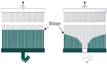
| 3. Draining condensate. Many combined cycle plant owners have retrofitted their superheater panels with high-capacity drains and added multiple drain connections to speed condensate removal and therefore quicken plant startup. Source: Tetra Engineering Group Inc. |
Over the past few years, HRSG purge issues have been extensively discussed at industry conferences. Some—in particular, a large segment of CC suppliers and operators—suggest eliminating the purge requirement on cycling units. However, the safety need for eliminating combustible gases remains. A concept for modifying the purge requirements to credit prior purges for cycling CCs was first introduced to the NFPA Technical Committee for Heat Recovery Steam Generators in 2003. The NFPA Boiler and Combustion Systems Hazards Code Committee established a task group in 2006 to pursue the idea and to enable CC operators to safely implement procedures that provide for a fast-start capability. The change in the code was finally issued in the 2011 Edition of NFPA 85 as the Combustion Turbine Purge Credit.
Calculating Purge Credits
The purge credit, simply defined, is when, during a normal CT shutdown, there is sufficient CT post-purge airflow to remove any residual combustible materials from the CT and HRSG system. If gases cannot seep into the ductwork, then the post-purge meets the NFPA requirements and a redundant start purge is not required.
In this scenario, the only concern is that leakage from the CT, duct burner, and/or the ammonia injection systems could travel into the CT and HRSG system after shutdown. To ensure that this extremely unlikely scenario never occurs, additional sealing valves and components are installed in the fuel systems. The final safety step in the design is to provide instrumentation and procedures to monitor the status of the isolation, assuming that the isolation is not inadvertently breached during unit shutdown. When these enhanced system isolation upgrades are completed, the revised NFPA 85 (2011) provides a purge credit that allows startup to proceed without an additional purge prior to CT light-off.
For traditional isolation of fuel supplies (gas and liquid fuels) in NFPA 85, a double block valve and vent piping arrangement has been required. The two block valves provided a positive isolation and the vent of the piping between them allowed gas to escape the isolated section. For implementing a purge credit, a triple block and vent valve arrangement is required. Three options are provided in NFPA 85 (2011):
- System 1 for gaseous fuels: Use triple block and vent valves with continuous monitoring of valve position, pressures in the two double block and vent valve pipe sections, and block valve validation for leak tightness by a valve-proving system (Figure 4).
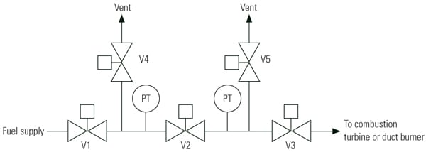 |
| 4. Purge system 1. Gaseous fuel triple block and double vent valve arrangement. Source: NFPA 85, Figure A.8.8.4.6.1 |
- System 2 for gaseous fuels: Use triple block and vent valves with pressurized pipe sections. The two pipe sections are filled with an inert gas or air at sufficient pressure to prevent fuel gas from entering. Continuous monitoring of valve positions and pressurized pipe section pressures is required (Figure 5).
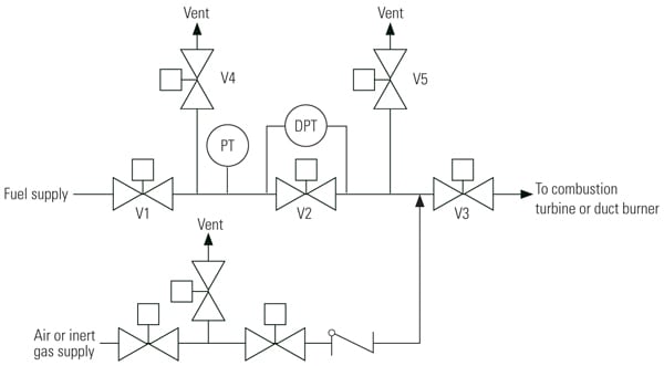 |
| 5. Purge system 2. Gaseous fuel with pressurized pipe section. Source: NFPA 85, Figure A.8.8.4.6.2 |
- System 3 for liquid fuels: Use a triple block and double drain valve arrangement filled with pressurized inert gas or air. Continuous monitoring of valve positions and pressurized pipe section pressures is required (Figure 6).
 |
| 6. Purge system 3. Liquid fuel with pressurized pipe section. Source: NFPA 85, Figure A.8.8.4.6.3 |
Comparing Isolation Options
The NPFA 85 purge systems 1 and 2 for gaseous fuels have different advantages and disadvantages. System 1 does not require a continuous supply of pressurized air or inert gas, but additional testing and monitoring must be performed (valve proving) to ensure system integrity. In addition, the purge credit can only be maintained for eight days, after which a purge must be performed to renew the credit. System 2 can maintain the purge credit indefinitely, but a continuous pressurized air or inert gas supply must be provided. If the supply is lost, the credit is no longer allowed. In both systems, the credit is lost if continuous monitoring of valve positions and pipe pressures is not maintained.
Purge system 3 can be used only for liquid fuels. It has pressurization and monitoring requirements similar to those of system 2 for gaseous fuels. In all three systems, each fuel supply must have similar isolation protection, including pilot gas and duct burner fuel supplies.
The primary benefit of the purge credit is fast system response. For an overnight shutdown resulting in hot start conditions, implementation of purge credit can shave 10 to 30 minutes off normal start-load times. Part of the time saving is the reduction of the purge time itself, and the rest is faster ramp rates due to a higher initial temperature and pressure in the HRSG. This design approach is now being used by several OEMs, including GE on its fast-start, flexible plant offerings. GE’s FlexEfficiency 50 offering is based on its FB-class CT with a single shaft generator and a single HRSG (see “GE Develops FlexEfficiency 50 for Increased Operational Flexibility” in the December 2011 issue or the POWER archives at https://www.powermag.com). GE offers purge credit with all the fast-response options (such as optimized high-pressure steam drums) and touts a 13- to 15-minute faster response than a typical CC plant. For older plants, greater startup time savings are possible.
Another tangible benefit is greater HRSG reliability and longevity. Daily cycling a CC plant typically means 150 to 250 starts per year. We estimate a 60% to 80% reduction in the hot/warm start contribution to steam drum fatigue (downcomer and steam outlet nozzles) and the hot/warm start contribution to superheater fatigue is reduced by a factor of 10. Much of these reduced fatigue estimates are a result of lower condensate production caused by unnecessary cold air purges and consequent thermal damage.
Exhaust gas path components, such as perforated plates and flow vanes, also see less fatigue damage. Purge reduction also lowers the use of electricity for startup (and purging), burns less natural gas, and reduces water consumption.
— David S. Moelling, PE (dave.moelling@tetra-eng.com) is chief engineer and Peter S. Jackson, PE (pjackson@tetraengineeringgroup.com) is director, field services for Tetra Engineering Group Inc.