Boilers have enormous thermal mass and are relatively slow to react. Turbines are nimble and quickly answer an operator’s command. Coordinating an entire plant requires an intimate knowledge of both systems and selecting the right logic tools to bring them together.
The front end, in the jargon of the power plant controls engineer, consists of the boiler master and turbine master. As explained in Part I of this two-part series, the operator’s window into the control system is referred to as a station or master, and it provides the operator interface for a given control loop. Access to that loop is typically from a switch or hand station located on the control panel in older plants or, more commonly, the operator’s keyboard in plants fortunate enough to be equipped with digital controls.
The best case is when both the turbine and boiler masters are in the distributed control system (DCS). But this is not always the case. We often find that only the boiler controls have been upgraded. In such cases it is important that the DCS be able to interface with the existing turbine controls if you want to take advantage of the DCS’s full abilities. Options for tuning the entire plant are limited with a DCS that includes the boiler master but lacks a communications link with the turbine controls.
Boiler Control Options
Boiler tuning is something of a balancing act. Feedwater enters the boiler through a series of low- and high-pressure steam heaters into the drum. The water then journeys through the water walls of the furnace and absorbs heat until steam is formed in the main steam drum.
This steam then enters the main steam line and passes through a series of superheaters and desuperheaters until it finally ends up at the turbine governor and/or stop valves. The boiler controls the turbine throttle pressure by modulating the boiler-firing rate. This means that the amount of fuel and air that is going into the furnace is increased or decreased depending on whether the turbine requires more or less steam pressure.
There are four usual modes of operation in the world of drum boilers: base mode, boiler-following mode, turbine-following mode, and coordinated control (Table 1). Each of these operating modes is described in the following paragraphs.
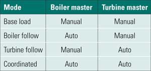
Table 1. Options for plant boiler control. Source: Tim Leopold
In general, the boiler master will be either in auto or manual control mode. The turbine is another matter. Turbine controls generally have a number of stand-alone loops — such as megawatt, pressure, valve position, or speed — which are control loops that do not respond to the DCS turbine master. If the turbine controls are not looking at the front end, then as far as the front end is concerned, the turbine is in manual control. For our purposes, "auto" under the turbine master heading in Table 1 means the front end is controlling the turbine governor valves.
Base Mode. In this mode, there is no automatic response to changes in main steam or throttle pressure or megawatt setpoint by the front-end controllers. An operator’s steady hand is required to make the final boiler control adjustments. The turbine might be in one of its own stand-alone loops, but the turbine master has no control of the plant. Many plants operate in this or a similar mode prior to upgrading their turbine controls to a DCS.
Boiler-Following Mode. In this mode of operation, the boiler master is in automatic and the turbine is not. This is an automatic control loop, controlling steam pressure. Depending on the boiler, it can be well controlled. Generally, this is the loosest of the three typical automatic front-end modes of operation (Figure 1).
1. Loaded questions. A typical boiler-following response following a setpoint change. Source: Tim Leopold
This is one of those loops that uses the dreaded derivative gain. The proportional gain is normally pretty high, the integral action slow, and the derivative is absolutely a must. The real keys to tuning the front end are a few simple concepts. For example, don’t add to an upset; that is, don’t have any of your gains disproportionately high. We use the derivative because we are trying to anticipate the steam pressure deviation.
The feedforward signal is an important part of this control loop and is often referred to as target steam flow. Target steam flow is the measured steam flow multiplied by the ratio of throttle pressure setpoint to throttle pressure. Typically, there is a function generator designed such that 0% to 100% of the input signal is proportional to a 0% to 100 % output signal. The nicely dynamic nature of the ratio helps the boiler master move in the right direction. Additional "kickers" may also be available. One option is a throttle pressure setpoint kicker that adds a little to the feedforward signal if the setpoint is changed. The derivative action of the controller also acts as a kicker.
Turbine-Following Mode. In many ways, this is my favorite plant operating mode, because it is the easiest to tune. It also offers a good strong safety net to operators in times of crisis. In turbine-following mode the boiler master is in manual and the turbine master is in automatic mode. The turbine master controls throttle pressure by modulating the turbine governor valves. Megawatts are then produced in the generator and pushed to the grid as a function of the boiler load.
Compared to the slow and sometimes lumbering response of the boiler, turbine response is usually fast and agile. Proportional gains are usually moderately large, and the integral action can be quite fast. Although adaptive tuning is possible, there usually isn’t the need for this; many units use only one value for the proportional and/or the integral gain. Also, the need for a feedforward is minimal. The turbine governor valves operate as one large pressure control valve that can easily control throttle pressure when the control loops are well-tuned.
Turbine-following mode is also a favorite among operators. If the plant is in coordinated mode, and the unit starts to go out of control for almost any reason, operators simply have to put the boiler master into manual. Immediately, the controls will automatically default to turbine-following mode. The valves open or close, as necessary to control the main steam pressure. Meanwhile, because the firing rate has steadied, the boiler controls will soon settle out.
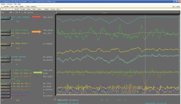
Figure 2 plots the data taken during start-up of a 320-MW power plant. At the lower left corner you can see where the valve transfer occurred. The valve transfer is a process in which the turbine, upon start-up, transfers control from the stop valve to the governor valve. There are actually two sets of valves in the main steam line before the turbine: the main stop valve and the governor valves. The next interesting point on this figure is the area that I call the "disturbing delta." There was a long period, during this load ramp, when the difference (delta), between the throttle pressure and the throttle pressure setpoint was virtually constant (the purple and green lines at the first vertical white dotted line). When we expect the controls to act one way, and they do not, it’s time to investigate.
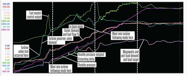
2. Under control. Taming a control loop that switched out the integral control on a load ramp. Source: Tim Leopold
During a change in unit load demand, in coordinated control, it is common practice to decrease the integral action of the boiler master controller to zero until the load ramp is finished. This strategy was used in all of the turbine and boiler master controller modes. This is a case where more is definitely not better; there was a touch of feedforward, based on boiler demand, substantial proportional gain, and no integral gain when I looked at the logic. Tuned as it was, the error signal between throttle pressure and throttle pressure setpoint will never go away.
I tried to tune out the error without success. Although the error decreased, as shown in Figure 2, we soon discovered that the tuning was not robust under all operating conditions. We then downloaded the necessary logic modifications (the second white vertical dotted line), causing the unit to drop out of turbine-following and into base load mode, and then back again. When the logic modifications were made, from that point on (the third white vertical dotted line) you can see good control of the throttle pressure. This is how a well-tuned turbine-following mode should operate.
Coordinated Control Mode
Coordinated front-end control was developed in the late 1970s and early 1980s to answer a long-standing controls problem. For many years, the turbine master controlled megawatt production and the boiler master controlled boiler pressure, and the two never spoke to one another. To this day there are plants that continue to operate with no coordination between the boiler and turbine masters.
For example, if we are in boiler-following mode, the boiler master is controlling pressure, and if the turbine master uses the local megawatt control loop, we have what I refer to as an "anti-coordinated" mode. If the megawatts increase, the turbine valves must close down. When the valves close, the throttle pressure rises. When the pressure rises, the boiler master must decrease. When the boiler decreases, the megawatts drop and the turbine valves must open up, dropping pressure, raising the boiler demand, increasing megawatts, closing the valves… and around we go again, and will hopelessly oscillate this way forever.
Enter boiler-turbine coordinated control, where the boiler master and turbine master are used in tandem to control both megawatt production and throttle pressure. In coordinated mode the boiler master looks mostly at the throttle pressure error and just a tiny bit of megawatt error. The turbine, on the other hand looks mostly at the megawatt error with some throttle pressure error. The expert tuning the controls must then decide how much of each to use. The rule of thumb, as passed on to me by Al Shultz, PhD, is 10 parts throttle pressure error to 1 part megawatt error for the boiler master; for the turbine it’s 10 parts megawatt error to 4 parts throttle pressure error.
If there is no coordination between the boiler and turbine controls, they will fight each other to the death. The boiler really cannot do much more than control throttle pressure, and even then it is slow because of its massive thermal capacitance.
The turbine valves are much faster and are capable of controlling both megawatts and pressure. The valves tap into the boiler’s thermal capacitance when the plant’s load changes. These ratios focus the turbine controls on megawatt production with the megawatt setpoint and throttle pressure are near the setpoint. When deviations occur, the throttle pressure error becomes more important and slows the turbine down, moving it in the opposite direction that a pure megawatt controller would demand. Amazingly, for all boilers (drum or once-through, coal- or gas- or oil-fired) this rule of thumb will give you a good solid starting point to begin tuning the front-end coordinated mode controls.
Next comes the tuning of the controllers. In general, the turbine master is the easier of the two components to tune, so that is the one to attack first. The gains will be less aggressive than were used for the turbine-following mode, but it is good practice to have the turbine master control the megawatts as tightly as possible at first. If that response is too much for the boiler to handle, the tuning can be loosened up later. Note that this will only be proportional and integral tuning with no derivative action.
The key to tuning the boiler master is balancing the proportional, integral, and derivative action of the controller so that the pressure is maintained with good control, moves toward the setpoint in a timely manner, and correctly anticipates the movement of the error signal. In general, the proportional gain will be fairly large, the integral action slow, and the derivative gain in the controller should be relatively small.
Finally, the controls that make up the coordinated front end may use some feedforward and the various kickers that are part of it. The feedforward signals to both the turbine and the boiler master controllers, in coordinated mode, is a function of unit load demand.
Tuning for Unit Response
Unit load demand is the high- and low-limited and rate-limited version of the unit master demand. The operator enters in his target megawatt load into the DCS. There are high and low limits on what the operator can enter that are determined by the operator, the boiler and turbine suppliers, and good practice. A unit load increase rate limit is also available to the operator. Typical values used by the industry are 1% or 2% per minute unit load rate of change. I have tuned boilers that can go up to 5% a minute, but nobody really uses that value because of the wear and tear on the equipment. I normally expect to see a rate limit of about 1 MW/minute for a 100-MW unit or 8 MW/minute for an 800-MW unit.
The feedforward to the turbine will usually be a very weak function of unit load demand, when used. This is because the turbine is quite capable of doing its part in this coordinated control dance — it can respond much faster than the boiler. The feedforward to the coordinated boiler master controller is quite different. The important aspect of feedforward is the slope of the line. This is determined by the function of unit load as well as the rate of change of the unit load demand chosen by the operator. This feedforward helps the boiler master keep up with the increase or decrease in load to maintain the throttle pressure at setpoint.
However, a simple feedforward addition is almost never sufficient for a robust coordinated control system. Remember that the boiler is a reservoir of energy trapped by the turbine governor valves as the load demand changes. However, it’s not an infinite reservoir, and the main steam pressure tends to sag or balloon as the unit increases and decreases load. That is why kicker circuits are included in the controls.
The first kicker is based on the feedforward (that is a function of unit load demand), and it should be a derivative kick that can be tuned to minimize the pressure sag on a load change. Remember, the closer the throttle pressure can stay to the setpoint, whatever it is, the easier it is for the turbine to provide megawatts and the less swing will occur when the load change is finished. Some boilers are well behaved and very responsive, so this kick is minimal. Some boilers are not well behaved, and their kickers can be pretty substantial. There can be other kickers, possibly based on the throttle pressure or the throttle pressure setpoint kicker, as described for the boiler-following mode.
Practical Controls Magic
The tuning process can’t be rushed and does take some time to get right. Here is an example. Recently, I walked into the control room of an 800-MW unit just as the operators made a load change. As you can see, the response of the unit left something to be desired (Figure 3).
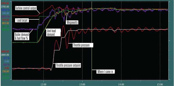
3. Unresponsive. A load change on this 800-MW unit showed poor response and controls in need of a good tuning. Source: Tim Leopold
By the third day, the coordinated controls were responding well after I slightly decreased the integral and proportional gain and increased the derivative action of the controller by about 25%. I also modified the feedforward signal slightly. Figure 4 illustrates the unit response to a 353-MW load increase test. About halfway through, the operator was unable to start an induced-draft (ID) fan, so he changed to base mode and then to boiler-following mode. When the ID fan was finally started, he returned to coordinated control mode. As you can see in Figure 4, a request was received by the front end to increase load just after the operator decided to raise his throttle pressure. This well-tuned boiler sailed through each test with rock-solid performance.
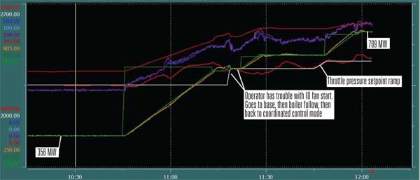
4. New lease on life. The same 800-MW unit as in Figure 3 showed much better response to a load change after tuning the proportional and integral gain and increasing the derivative action of the controller by 25%. Source: Tim Leopold
Runbacks and Rundowns
The final phase of tuning is runback testing. Turbine following is a nice safe place to retreat to when the operator has the time to take action. However, what happens when there is no time to react?
For these situations two control strategies are used: runbacks and rundowns. A runback is an action taken on a loss of a major piece of equipment. Typical runbacks include coal feeders, boiler feed pumps, or any plant fan — induced draft, forced draft (FD), or primary air.
A rundown is a reaction to a large process error that does not go away, such as a major boiler tube rupture. In this incident, the feedwater pumps pick up the increased feedwater demand or the feedwater valve goes completely open, but the drum level keeps dropping. Eventually, the plant must initiate a rundown or reduction in steam generation rather than trip the boiler. Typical rundowns are associated with air flow, furnace pressure, fuel flow, feedwater flow, or drum level.
Rundowns are seldom tested, on purpose, and that’s not because they are overlooked. Rather, the logic decides if the boiler or the turbine can or should respond. If the fuel master is in auto and looking at the boiler master for its output, then the boiler is capable of responding, and there is no need for the turbine to respond. If the turbine is not looking at the front-end controls for its output and the fuel master is not in auto, then the only device that can respond is the turbine, and so it does. This last scenario has a very high potential for tripping the unit.
Usually, the fuel master will be in auto. The boiler demand is then reduced by the rundown logic from where it was to some value that allows the error that is driving the rundown to fall below some preset limit. If the error does not go down, the rundown will continue to reduce boiler load to a set minimum value.
The first runback logic that I ever came into contact with was very severe. On a loss of equipment, the boiler controls would attempt to stay in coordinated mode. The unit load demand would run down, at some preset, fast, rate. This would decrease the boiler demand and the demand to the turbine governor valves. That worked all right for some boilers, but the rate that was necessary for the boiler to get to a safe operating load was very fast. The difficulty is that the turbine governor valve would close down at the same rate. When these valves close, the main steam pressure must climb and may eventually lift the boiler pressure safety relief valves. This is very hard on the drum level and your ears, and often results in a master fuel trip. Granted, it was a trip from a lower boiler load, rather than if we had otherwise simply tripped the boiler, but it was a trip nonetheless.
As a result, what I like to call a kinder, gentler runback was developed. Some call it the turbine-following runback, where the boiler switches to manual on the loss of a piece of equipment. If you are in coordinated mode, the boiler should go to manual control and turbine-following mode for the steam turbine. At this time, the runback logic reduces the boiler demand to a predetermined level at a preset rate. In the meantime, the turbine is free to control the main steam pressure. The megawatt load is then gently reduced, and the plant experiences a soft landing. Turbine-following is the best mode to select in an emergency.
A further goal of a runback is to recover automatically so the operators can figure out what happened to the equipment and fix it while the unit is still online and avoid a master fuel trip.
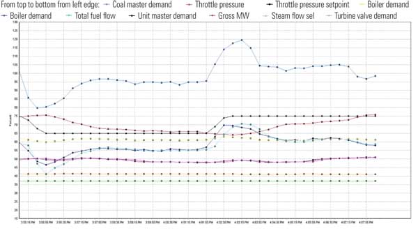
The data shown in Figure 5 were collected during an actual runback test on a 95-MW plant that operated with three pulverizers. The runback occurred when an ID fan was tripped, which had the effect of tripping one of the FD fans. The runback of the boiler was set to a point that was below the three-mill minimum load for safe and stable operation. As a result, automatic mill tripping on a runback was developed.
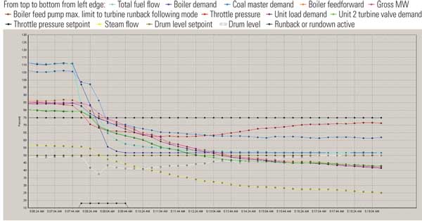
5. Avoiding unit trips. A runback test is necessary when any changes are made to boiler gas pass, fans, or mills. In this test of a 95-MW unit, the runback occurred when an ID fan was tripped. Source: Tim Leopold
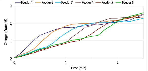
You can see the boiler demand dropping, and the fuel flow percentage dropping even further as one of the three mills is shut down by the runback logic. The pulverizer master (coal master demand) picks up momentarily as the mill is stopped, then ramps back down, eventually getting the fuel percentage down to the boiler demand. Automatic mill tripping is generally a good idea, especially on larger units with a lot of mill capacity. Also, notice how the turbine pushes the throttle pressure back to the setpoint. Drum level also dropped slightly before it recovered. The entire runback occurred in just over two minutes. Figure 6 is a longer view of the entire episode.
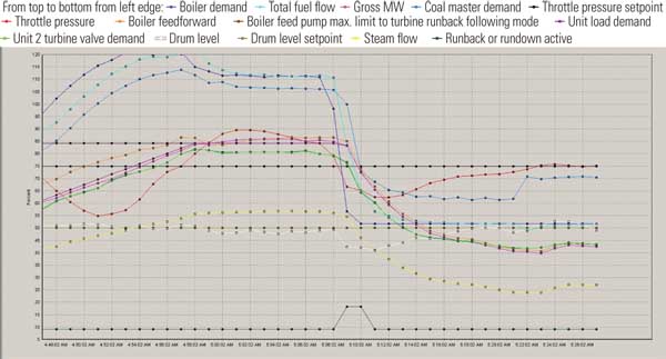
6. Many moving parts. The same runback test (Figure 5) of a 95-MW unit but with a longer time-span is illustrated. Here you can see the pulverizer master ramping back and the lowering of the turbine operating pressure setpoint. Source: Tim Leopold
In this test, as is true for most of the tests I have run over the years, the fan and fuel runbacks are easily handled by the turbine-following runback logic. However, the boiler feedwater pump runback can be another matter. The turbine valves are relatively slow to respond and tend to suck steam from the drum. Though some boilers are able to survive this without tripping on low drum level, many can not.
As a result, new logic was developed. I like to call this special type of runback the separated runback. On the loss of a boiler feed pump, the boiler master goes to manual, coal mills are tripped, and the boiler demand is driven to minimum. The turbine master remains in auto to stay in turbine-following mode. At this point, we add a special high-limit override enabled during this runback that overrides the turbine-following controller and marches the governor valves to a predetermined position. The rate at which the valves are closed is variable and depends on the throttle pressure. Higher pressures tend to depress the drum level, which we do not want, and really high pressures lift safeties, which started us on this runback logic journey in the first place.
If you plan to test your runback logic, it’s a good idea to elevate the drum level a few inches before your test. At this same 95-MW plant, we tested the boiler feedwater pump runback using separated runback logic from 75% load with the drum level rundown initiated when the runback was complete. Figure 7 data illustrate this successful test from the feedwater perspective. Notice the action of the feedwater control valve. The drum level dropped about 6.5 inches. The low drum level trip was set at 7.7 inches. That was successful, but a little too close for comfort.
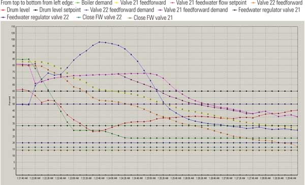
7. Different perspective. The same runback test (see Figure 5) of a 95-MW unit but from the perspective of the feedwater system. Note the drum level response. Source: Tim Leopold
When Enough Is Enough
One of the big challenges faced by a boiler and turbine controls tuner is to know when to stop. It’s a job that has no defined stopping point, and there are always ways to further improve performance.
So how do we know when boiler tuning is finished? Typically, I call it quits when the operators are satisfied and, based on my experience, the plant is as good as other units I’ve worked on over the years. Or, in the words of Supreme Court Justice Potter Stewart, "I know it when I see it."
—Tim Leopold (tim.leopold@hotmail.com) is a field service engineer with ABB and has more than 20 years’ experience tuning controls on power plants around the world. His book, You Can Tune a Boiler But You Can’t Tuna Fish, is available through amazon.com.