Thermal insulation is installed on almost every piping system and much of the plant equipment at power generation facilities. It not only saves energy, but also protects workers, reduces noise, helps protect against freezing, and more. However, determining the most cost-effective thermal insulation solution can be difficult. Completing a few calculations can help ensure systems and personnel are adequately protected while optimizing process variables.
Thermal insulation is mainly used to limit heat loss from hot surfaces and heat gain on cold surfaces. In addition, thermal insulation also serves to provide condensation (anti-sweat) control, protection for personnel, freeze protection, fire protection, noise control, and process control.
This article explains the basic calculations associated with the design of thermal insulation for hot and cold pipes, including surface temperature and freeze protection calculations. Energy savings estimates and the specific requirements for cold insulation and jacketing are also presented.
Basic Heat Transfer Calculations
Heat flows in the direction of the temperature gradient and the relationships governing heat flow depend on whether the heat transfer is occurring by conduction, convection, or radiation. These mechanisms for heat transfer are discussed below with sources of equations, such as the American Society of Heating, Refrigerating and Air-Conditioning Engineers (ASHRAE), appropriately noted.
Conductive Heat Transfer Through a Flat Slab. The basic equation for conductive heat loss or gain through a flat slab is given by the following equation, which can be found in the 2013 ASHRAE Handbook: Fundamentals, I-P Edition:
Q = k x A x (T1 – T2) / X
where Q is the heat loss or gain (Btu/hr); k is the thermal conductivity (Btu-in./hr-ft2-F); A is the area of heat flow (ft2); T1 – T2 is the temperature difference (F); and X is the thickness of material (in.).
Conductive Heat Transfer Through a Hollow Cylinder. The basic equation for conductive heat loss or gain through a hollow cylinder, also found in the 2013 ASHRAE handbook, is similar with a slight change in the value of X and A, as shown below:
Q = k x A2 x (T1 – T2) / (r2 x ln (r2 / r1))
where Q is the heat loss or gain (Btu/hr); k is the thermal conductivity (Btu-in./hr-ft2-F); T1 – T2 is the temperature difference (F); A2 is the area of outer surface (ft2); r2 is the radius of outer surface (in.); and r1 is the radius of inner surface (in.).
The above equations for heat loss and gain through a flat slab and a hollow cylinder are based on conductive heat transfer only. However, the heat transfer from the surface to the environment involves convection and radiation as well. This is shown in the equation below for heat transfer through an insulated pipe.
Total Heat Transfer Through Insulated Pipe. The basic heat transfer equation for heat loss based on conduction through the metal pipe and insulation, and convection at the inside fluid film and the outside insulation surface air film is given as follows, obtained from the Mechanical Engineering Reference Manual for the PE Exam, 12th Edition, written by Michael R. Lindeburg, PE:
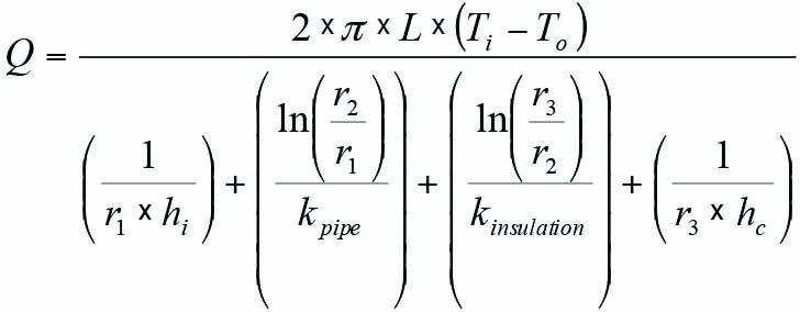
where Q is the total heat loss (Btu/hr); L is the length of pipe (ft); Ti is the temperature of fluid inside pipe (F); To is the temperature of outside environment (F); r1 is the inside radius of pipe (ft); r2 is the outside radius of pipe (ft); r3 is the outside radius of insulation (ft); hi is the inside film coefficient (Btu/hr-ft2-F); hc is the outside convective film coefficient (Btu/hr-ft2-F); kpipe is the thermal conductivity of pipe material (Btu/hr-ft-F); and kinsulation is the thermal conductivity of insulating material (Btu/hr-ft-F).
Convective Heat Transfer and Radiant Heat Transfer from Outer Surface of Insulated Pipe. The convective heat transfer coefficient and the radiant heat transfer coefficient determine the heat loss or gain from the outer surface of the insulation (or pipe, if uninsulated) to the ambient atmosphere. The heat loss equation from the 2013 ASHRAE handbook is given by:
QCR = (hc + hr) x A3 x (Tsurf – Tamb)
where QCR is the convective and radiant heat transfer (Btu/hr); Tsurf is the temperature of the surface in contact with ambient (F); Tamb is the ambient temperature (F); hc is the convective heat transfer coefficient (Btu/hr-ft2-F); hr is the radiant heat transfer coefficient (Btu/hr-ft2-F); and A3 is the outer surface area (ft2).
The convective heat transfer coefficient (hc) for the outside air film can be calculated by several methods. The most common method is to use a correlation involving dimensionless numbers in the Nusselt equation in the following form:
Nusselt No. = C x (Grashof No. x Prandtl No.)n
wherein the convective heat transfer coefficient hc is a parameter within the Nusselt No., and C and n are constants.
However, a more convenient form for calculating the convective heat transfer coefficient is given in the 2001 ASHRAE Handbook: Fundamentals, I-P Edition, as follows:
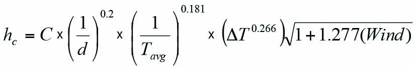
where hc is the convection heat transfer coefficient (Btu/hr-ft2-F); C is a constant ranging from 0.89 to 1.79 depending on the shape and orientation of heat flow; d is the diameter of the pipe (in.); Tavg is the average temperature of the air film (R), that is, Tavg = (Tamb + Tsurf) / 2; ΔT is the temperature difference between Tsurf and Tamb (R); and Wind is the air speed (miles/hr). For flat surfaces and large cylinders (d > 24 in.), use d = 24 in.
The radiant heat transfer coefficient (hr) found in the 2013 ASHRAE handbook is given by:
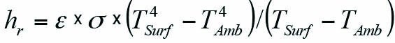
where ε is the surface emittance; σ is the Stefen-Boltzmann Constant (0.1714 x 10⁻⁸ Btu/hr-ft2-R4); TSurf and TAmb are temperature (R).
Energy Savings Due to Insulation. The heat loss in still air from a bare hot pipe with a temperature difference in the range of 300F to 450F is expected to be around 1,000–2,000 Btu/hr-ft2. By providing insulation on such a pipe, the heat loss can be reduced to an acceptable level of around 100 Btu/hr-ft2.
The desirable heat gain in cold piping (except chilled water) is generally limited to around 10 Btu/hr-ft2 depending on energy costs while somewhat higher values (around 40 Btu/hr-ft2) are used for chilled water. With cold insulation meeting these requirements, it is likely that this will also prevent surface condensation most of the time. The surface condensation will be prevented as long as the surface temperature remains above the dew point temperature. The surface temperature can be calculated as shown below.
Surface Temperature Calculation. In addition to minimizing heat loss or gain, thermal insulation provides several other useful functions. One such function is to limit the surface temperature. In the case of hot insulation, the surface temperature must be limited to below 140F (or more preferably 125F) to protect personnel from potentially irreversible injury.
In the case of cold insulation, the surface temperature should be sufficiently higher than the ambient dew point if surface condensation is to be limited or retarded.
The surface temperature can be calculated by considering a steady state energy balance. For hot insulation, the heat flow through the insulation equals the heat flow from the outer surface of the insulation to the ambient air. For cold insulation, the heat flow from the ambient to the outer surface of the insulation equals heat flow through the insulation.
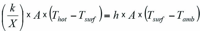
The thickness (X) of insulation required to achieve a desired surface temperature can be determined from the following energy balance, where h is the combined convective plus radiant heat transfer coefficient.
Heat transfer Q (Btu/hr) for a flat insulation surface as noted in the 2013 ASHRAE handbook is equal to:
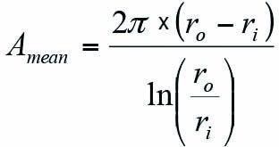
For a radial surface of unit length, the left-hand side (LHS) of the flat-surface equation after substitution becomes:
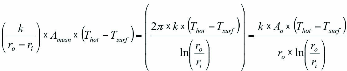
where ro is the outside radius of insulation and ri is the inside radius of insulation.
The above formulation for the radial surface equation is arrived at by substituting the following from Lindeburg’s manual:
and
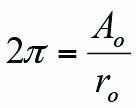
As a result, the energy balance equality: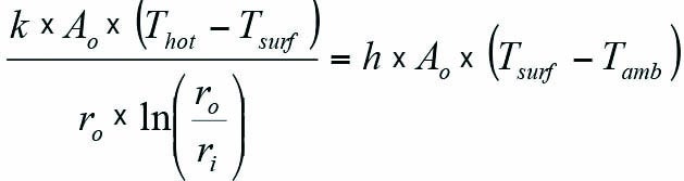
provides the relationship for calculating the insulation surface temperature Tsurf for various insulation thicknesses and thermal conductivities. However, the calculation for Tsurf requires a trial-and-error solution, and the maximum value for Tsurf is generally limited to 140F (or preferably 125F) to prevent personnel injury from irreversible burns.
Insulating for Freeze Protection of Piping. During cold weather, piping exposed to low temperatures is subject to freezing. Use of insulation can extend the time to freeze, but the pipe under no-flow conditions will ultimately reach the freezing point. In such cases, heat tracing plus insulation can be used to prevent pipes from freezing, even during extended periods of time under no-flow conditions at below-freezing temperatures.
The heat lost through the insulation must be compensated for by heat added using heat tracing tape or elements. Typical low-power heat trace tape wattage is between 3 watts per linear foot and 10 watts per linear foot. The heating cables are self-regulating with power output responding variably to temperature. Increasing the insulation thickness can decrease the heat trace load. Nevertheless, a point is reached when additional insulation is not cost-effective.
In the case of flowing lines, heat is constantly being added by inflow of warmer fluid, and in most cases freezing is not an issue. However, fluid can reach a potentially problematic low temperature if the length of the pipe is long or if any drop in process temperature is intolerable.
To calculate the time to freeze of a nonflow line, ASHRAE’s 2013 handbook provides the following equation:
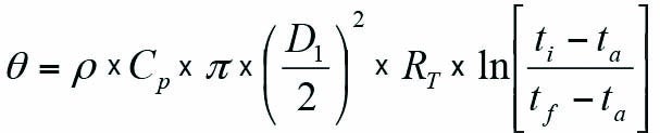
where θ is the time to freezing (hr); ρ is the density of water (lb/ft3); Cp is the specific heat of water (1.0 Btu/lb-F); D1 is the inside diameter of the pipe (ft); ti is the initial water temperature (F); ta is the ambient air temperature (F); tf is the freezing temperature (F); and RT is the combined thermal resistance of the pipe wall, insulation, and outside air film (ft-F-hr/Btu). Ice formation occurs when the temperature reaches the freezing point and the fluid loses additional heat in the form of latent heat of fusion for ice (144 Btu/lb) through the insulated pipe.
In addition to the above equation for determining time to freeze, ASHRAE provides tables showing insulation thicknesses for various pipe sizes and time to cool still water to freezing. The tables are based on initial water temperature of 42F with ambient at –18F and using insulation with thermal conductivity of 0.025 Btu/hr-ft-F. For cases with flowing water, the tables also show the water mass flow rate per unit length of exposed pipe to prevent freezing based on initial water temperature of 42F. In case it becomes impractical to avoid freezing with insulation alone, heat tracing is utilized to compensate for the heat loss through the insulation.
Cold Insulation
Cold insulation refers to insulation installed on piping and equipment operating below ambient temperatures. The main difference between hot and cold insulation is that with cold insulation there is the possibility of creating a water vapor pressure gradient, which could drive the water vapor through the insulation to the cold metal surface. This could lead to accumulation of water within the insulation and on the surface of the piping, which could degrade the insulation and pipe surface.
To counter the effect of water vapor migration, closed-cell insulation material is recommended for cold insulation applications so that it resists moisture absorption or wicking. In addition, moisture vapor stops are used to isolate insulation sections and limit the area of damage, if it occurs. Also, a vapor retarder jacket is used but it must be continuous and sealed at all seams and joints to provide effective protection against moisture ingress.
Insulation Jacket
The insulation jacket provides the outer covering for the insulation and functions to protect the insulation from mechanical damage and moisture ingress. The commonly used material for the insulation jacket is aluminum. However, aluminum has a low melting point and therefore is not suited for use under fire conditions. For cases where fire risk is present, stainless steel jacketing is used, which has a significantly higher melting point.
Aluminum jacketing is available with various surface finishes such as smooth, stucco-embossed, or corrugated. Ingress of water has the potential to corrode the aluminum jacket from the inside. Therefore, aluminum jackets are often provided with an inner layer of nonpermeable material (moisture barrier), which protects the jacket from moisture corrosion from the inside.
If jacket corrosion is an issue, other material such as thermoplastics, fabrics, or synthetic rubber can be utilized. The various jacket materials have different emissivity and this has an effect on heat transfer performance. Polished metals have lower emissivity whereas plastics, such as PVC (polyvinyl chloride) or fabric-mastic layer, have higher emissivity.
High emissivity results in higher heat loss from the hot-source pipe or equipment. In low-temperature systems, higher emissivity jackets result in higher heat gain by the cold pipe. For anti-sweat insulation and personnel protection insulation, high-emissivity jackets tend to reduce the required insulation thickness.
Thermal insulation is also important for noise control and for fire protection. Sound attenuation is a natural attribute of insulation material and jacketing. For fire protection, metal jackets and bands, as mentioned previously, are made of stainless steel, and they are fixed to ensure that they can withstand the impact from a firefighting water stream. ■
—S. Zaheer Akhtar, PE is principal engineer-mechanical with Bechtel Corp.