An adiabatic cooling tower system can save great amounts of water at power plants compared to typical wet-type cooling towers. While there are challenges to implementation, understanding how these systems work and the benefits that can be captured with them will help decision-makers better evaluate their options.
There is more concern today than ever around water usage at power plants. When water resources were more abundant, using open-cycle cooling towers posed few problems. However, times have changed and cooling tower water consumption is often heavily scrutinized at plants today.
It has been observed that between 2,900 liters and 3,000 liters of water evaporate from cooling towers to produce one megawatt-hour of electrical power. That adds up to a lot of water at modern facilities with capacities in the thousands of megawatts.
The ACC Option
A few decades ago, some thermal power stations began installing air-cooled condensers (ACCs). These condensers are very effective at saving water, but there are limitations. When ambient temperatures reach about 40C to 45C, the cooling capacity of these condensers gets derated. If an ACC is installed in a high-temperature climate, there is a huge capacity reduction. This can be easily understood using the following universal equation:
P = k x A x LMTD
where P is the heat load, k is the heat transfer coefficient, A is the heat transfer area, and LMTD is the log mean temperature difference. The heat transfer coefficient depends on the type of metals used, air-side velocity, and velocity of steam flowing inside the tubes, so it more or less remains constant, as the design does not change at the higher ambient temperature. The heat transfer area is the area of fin and tubes on the ACC. Assuming a like-for-like installation, it would be identical in the higher ambient location. The log mean temperature difference, however, increases or decreases with the change in the air temperature—the lower the ambient temperature, the higher the LMTD, and vice versa.
ACCs are typically designed for some fixed highest ambient temperature. When the ambient temperature goes higher than the designed temperature, then the LMTD decreases and there is more surface demanded to dissipate heat. Because the area of the ACC cannot be changed, plant operators must reduce the inlet steam quantity, which causes the derating of the power plant.
When ACCs are designed for a higher ambient temperature, the surfaces needed grow considerably larger, and so does the footprint and power required to run fans. This has a direct impact on the cost of the units, and sometimes it is not viable to install an ACC.
Dry Coolers
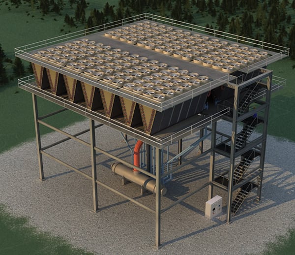
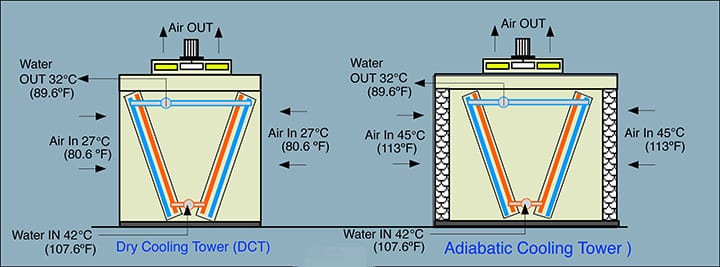
An adiabatic cooler is another option that has been developed to reduce water consumption. To understand the adiabatic cooling concept, first a person must understand the concept of a dry cooler, or a direct cooling tower (DCT, Figure 1).
 |
|
1. A comparison of a dry cooling tower versus an adiabatic cooling tower. Courtesy: Kojami Power |
A DCT, also called a fin fan cooler in the thermal industry, is a dry system where the process water flows in a closed loop. The process water is not exposed to the ambient air. This type of cooling tower works purely on the principle of approach temperature, which refers to the temperature difference between the outlet of one stream (such as water being cooled) and the inlet of the other (such as ambient air passing across the fins). The formula for this calculation is:
Delta (A) approach = Water out (from cooler) – Maximum ambient temperature
The minimum Delta A required has to be between 3C and 5C. The higher the approach, the lower the surface area required, and vice versa. Because air is the only media of cooling in a DCT, Delta A cannot be zero or negative.
There are two kinds of dry coolers: one is an induced draft and the other is a forced draft. In an induced draft dry cooler, the fans draw the air from the coils. In the forced draft, the air is blown over the heat exchanger.
Dry coolers cannot cool the water below the ambient air temperature. If the temperature of the water must be reduced below the ambient air temperature, then an adiabatic system must be added to the dry cooler. In the adiabatic system, the ambient air is first cooled with the help of water spraying, then it is passed to the dry-cooling section of the cooler.
For example, assume the ambient temperature is 45C (113F) dry-bulb temperature (DBT) at 15% relative humidity (RH) at 23.96C (75.12F) wet-bulb temperature (WBT). If the present open-cycle wet-type cooling tower, which is operating at 42C (107.6F) and 32C (89.6F) as water outlet conditions, is to be replaced by a dry-cooling system, then an adiabatic system must be installed in front of the DCT.
Adding Adiabatic Cooling to a DCT
When the adiabatic system is installed in front of the DCT, the ambient air first comes in contact and interacts with the water-cooling system. At this point first, the sensible load is removed from the air, which means the dry-bulb temperature decreases. The principle is based on evaporation cooling. The hot air coming from ambient air acts as a heat source, and when it interacts with the water droplets, it evaporates, so there is a phase change in the air. The hot air becomes colder, saturated air.
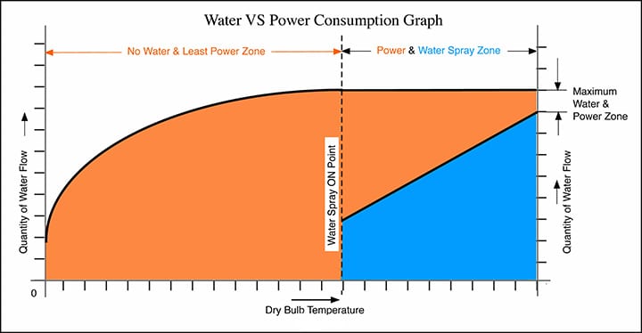
For example, to achieve 32C (89.6F) of water outlet from the cooler, an air inlet of 27C or 28C (80.6F or 82.4F) is needed. When the air at 45C DBT (113F) at 15% RH enters the system, it acts as the energy that evaporates the water. The sensible heat gets converted to latent heat. To evaporate 0.454 kilograms (1 lb) of water, 284.27 W (970 Btu) is needed. When the incoming air is at 45C (113F) at 15% RH, the outlet water temperature has to be at 27C (80.6F) by design. The airflow passing over the spray systems has to be calculated for these temperature profiles. Below 27C (80.6F) there will be no water required.
When designing an adiabatic system, caution must be taken to note the temperature profile of all 8,760 hours in the year. The water consumption may vary every hour. Once a detail chart is prepared, a graph of water versus power consumption can be generated (Figure 2).
 |
|
2. This graph shows the water versus power consumption for a reference adiabatic cooling tower. Courtesy: Kojami Power |
Connecting Adiabatic Cooling to Open-Cycle Cooling Towers
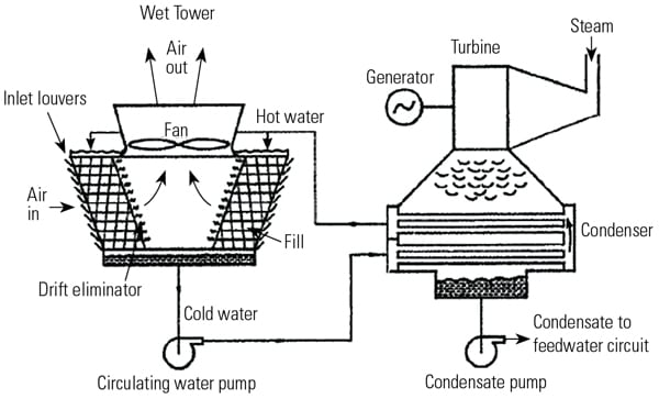
It is very easy to connect an adiabatic cooling tower (ACT) in parallel with existing cooling towers; three-way valves are all that is needed on the water inlet and outlet of the wet-type cooling tower and ACT (Figure 3). This will also serve as double safety. It means, whenever there is some maintenance issue in the ACT, the water can be cooled by the existing wet-type cooling tower.
 |
|
3. This diagram shows how an adiabatic cooling tower could be added to a plant with an existing wet-type cooling tower. Courtesy: Kojami Power |
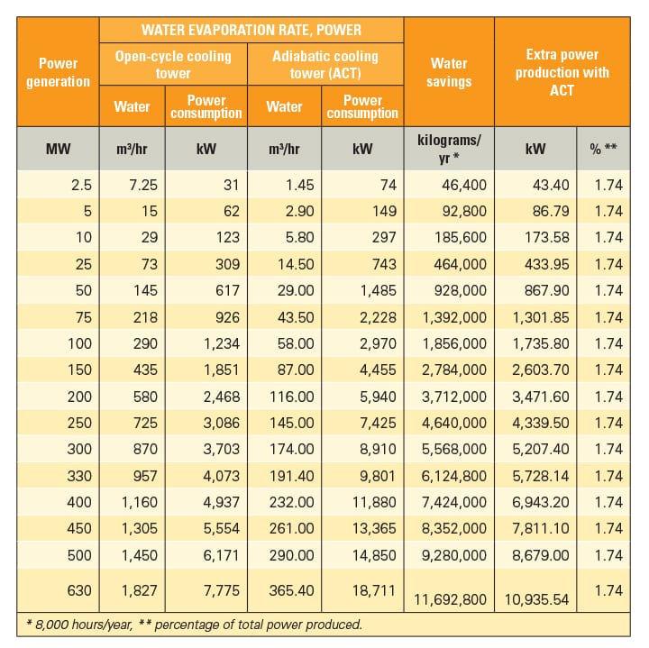
Table 1 demonstrates how much water and power are consumed while running typical thermal power stations. For example, when an open-cycle cooling tower is used to produce 100 MWh of power generation, the water consumption (evaporation) equals 290 cubic meters, which is a 1.9% loss because of drift losses. The fan power required is 1,234 kWh.
 |
|
Table 1. A comparison of water and power consumption is shown here for thermal power plants using open-cycle or adiabatic cooling towers. Courtesy: Kojami Power |
When an ACT is connected to the system, the water consumption comes to 58 cubic meters, and the power consumption equals 2,970 kWh. The water consumption is reduced by 80% and the power has increased by 41%. However, the extra power consumed by the ACT is somewhat misleading, because when the extra power produced while using the ACT is factored in, the net power consumption increase is only 1.74%, which is nearly negligible when compared to the water saved.
Over the past few years, many companies have adopted different methods of pre-cooling the air used in ACTs. Some companies have used direct water spraying on the fin tube blocks (FTBs), some companies used fogging systems, many started using paper pads, and a few have installed plastic pads. All the systems have great limitations.
The direct spray of water on the FTBs spoils the quality of fins, and over a period, deposits of salt can be seen on the FTBs. To overcome this problem companies started using fogging systems. This also has great limitations because a high-pressure pumping system is required and the quality of water has to be monitored continuously.
A very large company also started experimenting with paper or plastic pad systems in front of FTBs. This is an efficient system on the initial days of installations, but as time passes, the system starts becoming de-rated. This is because there is no control over the ambient air. Paper pads are more efficient than plastic pads, but the life of paper pads is no more than two to three years.
Another problem with present ACT suppliers is that most manufacture small sizes of ACT. After conducting a detailed study worldwide, very few companies were found that can build a large-scale ACT. The research found the maximum water that can be handled presently was 230 cubic meters per hour (m3/hr) per ACT. As a thumb rule, a minimum of 150 m3/hr/MW is needed, so if a company wanted to install ACTs on a 100-MW power plant, then the total number of units needed would be about 66 ACTs (150 m3/hr/MW x 100 MW / 230 m3/hr = 65.2 ACTs).
Furthermore, the power required would be 135 kW per unit. Therefore, the total power required would be 8,910 kW/MW (installed). Even if variable frequency drives were utilized and the extra power production was factored in, the minimum power required would not be less than 4,455 kW, which is 4.455% of the total power produced by the plant.
Thus, with the present technology, a 100-MW thermal power plant would require 66 ACTs, which have three fans each, thereby totaling 198 fans, which adds another maintenance concern. The minimum space required would be 7,500 m2, a fairly significant space for a 100-MW facility. This is the main reason why power plants are not very comfortable using this technology currently with present manufacturing setups.
Ultimately, the answer is to use larger coolers with larger diameter fans (such as with 10-meter blade diameters) to overcome the power consumption problem. This larger unit could handle about 550 m3/hr of water (at a typical power plant). It means for a 100-MW plant, only 28 coolers would be required, with only 28 fans.
These coolers have metallic pads made out of stainless steel, which is a life-long solution, and the power consumption is about 2,970 kW per 100 MW. This is about 2.31% of the total power production of 100 MW. The water consumption is 80% less when compared to wet-type cooling towers, and the space required totals 5,300 m2 for 100 MW. Contact the authors via email (jss@kojamipower.eu) to learn more. ■
—Dr. Jagjit Singh Sehra is a director with Kojami Power in Germany. He has spent nearly 40 years in the field of heat transfer and has worked with many power companies including NTPC, BHEL, PDO Oman, and Kuwait National Refineries, among others. Michael Kost is also a director with Kojami Power. He has spent nearly 25 years selling and installing dry and adiabatic coolers at many power plants
in Europe and the Middle East.