Recent Nuclear Regulatory Commission (NRC) Component Design Bases Inspection activities have scrutinized empirical approaches used to determine vortex allowances for emergency core cooling system (ECCS) suction sources. In 2006, the NRC asked nuclear plant operators to review their analysis of the tanks in their ECCS and containment spray systems (CSS). The NRC wanted to verify that plant designs were adequate to ensure that any vortices formed during draw-down of the fluid would not result in pump air ingestion (see sidebar). Duke Energy Corp. of Charlotte, N.C., opted to perform rigorous physical scale model testing to demonstrate adequate vortex allowances were present in its designs.
"The ECCS includes a variety of different pump designs: some are single-stage centrifugal, some are multi-stage pumps — and the latter are very intolerant to air ingestion," says Bryan Meyer, principal engineer in the Primary Systems Engineering Group at Duke Energy’s McGuire Nuclear Station.
To demonstrate that its cooling systems could operate safely, Duke Energy engaged Alden Research Laboratories (Alden) of Holden, Mass., to conduct physical modeling of its refueling water storage tanks (RWST). The tanks were found to be well within the margin of safety.
"The physical modeling allowed us to recover additional margin in our usable tank inventory and reduce our vortex allowance dramatically," says Meyer.
Modeling Vortices
For many utilities, once the NRC issued Information Notice 2006-21, Operating Experience Regarding Entrainment of Air into Emergency Core Cooling and Containment Spray Systems, the first action was to conduct a literature search to determine if existing research could validate their system designs without having to conduct individual testing. In most cases, this proved fruitless.
"It’s not a case where one size fits all," says Andrew Johansson, Alden’s director of hydraulic modeling. "The flow rates vary, the plant geometries vary, and so the results are dependent on those flow rates as well as plant-specific geometries."
Some utilities have expressed an interest in parametric testing that would guide decision-making. To date, no such studies have been carried out. Another option was to use computational fluid dynamics (CFD). However, this wouldn’t deliver the accurate, defensible results required. CFD has come a long way over the past decade as increasingly powerful computers make it possible to model flows with higher precision. One issue they have not yet been able to solve, however, is vortex formation.
"Vortex formation is unstable, and CFD models are unable to predict the unsteady nature of the vortex," says Johansson.
In addition, although CFD may be able to show a swirl beginning within the cooling water, it can’t show whether or not that swirl poses a problem. There are six different levels of vortices, ranging from Type 1, where water is swirling on the surface, to Type 6, where there is a full air core reaching from the surface into the intake. Types 1 through 4 don’t pose a problem of air entrainment. Type 5 (vortex pulling air bubbles to intake) and Type 6 can be disastrous (Figure 4).
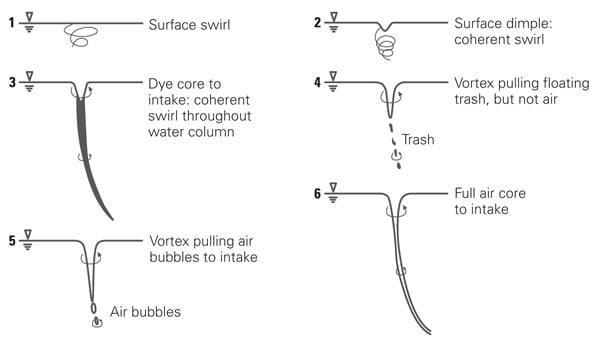
4. Vortex classification. Vortex types 1 through 4 are common and usually don’t cause damage to the pump. Vortex types 5 and 6 ingest air into the pump and can cause significant damage to a pump. Source: Alden Labs
"Even if you did a CFD study and could predict vortexing, you would not know whether it was just a surface rotation or something stronger like a vortex drawing air bubbles or a full air-core vortex pulling air into the inlet," says Johansson.
The only way to determine if a vortex will form and whether it will cause a problem, is to build a scale model simulating the geometry of the tank, the size and shape of the inlet nozzles, and the flow rate of the pumps. In doing so, it is essential to have a tank that is large enough to create an accurate simulation, but not so large that it becomes cost prohibitive. The models are constructed using Froude (Fr) number similarity, because the flow process is controlled by gravity and inertia. The Froude number is calculated by dividing the average velocity at the intake (V) by the square root of gravitational acceleration (g) times the average intake diameter (L): Fr = V ÷ √(gL).
As long as the scale model is large enough to minimize any viscous or surface tension effects, by keeping Fr constant, the flow patterns in the hydraulic model will simulate those in the plant. For nuclear tank draw-down models, a scale of 1:2 to 1:5 generally meets these requirements.
Building the Model
Duke Energy Corp. owns and operates three nuclear stations — Catawba, McGuire, and Oconee — and opted to perform physical scale model testing for all three stations.
"The system design requires that the RWST suction piping remain water-filled during drawdown, such that no air ingestion occurs," says Meyer. "We must transfer pumps from the tank prior to the pipe becoming voided."
The company considered using CFD but eventually opted for hydraulic modeling. Alden was ultimately selected to perform the scale model testing. "Alden proposed the most rigorous modeling and technical approach," says Meyer.
Alden, which has been conducting hydraulics research for more than a century, has an established reputation with the NRC and has an on-site calibration laboratory to ensure that all measurements are accurate. Flow meter calibrations are done using equipment that is NIST (National Institute of Standards and Technology) traceable and accurate to within 0.25%.
Because several different tanks with different geometries needed to be modeled, Alden utilized a circular tank with a diameter of approximately 10 feet at the bottom and a depth of approximately 5.5 feet, which would allow simulation of different depths. For the McGuire station, which consists of two 1,100-MW Westinghouse pressurized water reactors with wet/ice containment, a model-scale of 1:4.073 was used.
The 24-inch primary outlet pipe, which is installed at a 45 degree angle, with the elliptical entrance 12 inches above the tank bottom, was modeled using acrylic pipe. The installation of clear acrylic piping enabled visual observations of air entrainment. A flow loop could operate closed, fully open, or partially open. Partial return flow controls the rate of draw-down in the water tank, with the rest of the water going to the laboratory sump. Because water and acrylic have nearly identical refractive indexes, a rectangular acrylic viewing box was installed around the outlet pipe to compensate for the visual distortion of the curved pipe and to allow for good viewing and videotaping of the air bubbles (Figure 5).
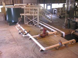
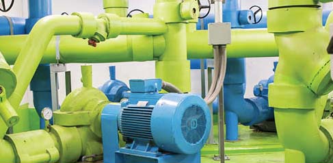
5. Scale models. Alden Labs designed a scale model test of the pump suction at the Duke Energy nuclear plants. Duke Energy elected to develop scale models to determine vortex allowances for its three plants’ emergency core cooling systems and containment spray systems to demonstrate that their pump suction designs ensure that any vortices formed during drawdown of the fluid would not result in pump air ingestion. Courtesy: Alden Labs
A series of 10 tests were run at prototype flow rates from 1,600 gpm to 19,700 gpm. Five of the tests were conducted with a return flow rate representing a water level drop of about 0.5 inch per minute, and five were done with the return pipe closed.
The tests showed that the tank could safely operate at much lower water levels than required by ANSI’s Hydraulic Institute Standards (HIS). Whereas the HIS specified a submergence of 2.85 feet for a flow of 1,600 gpm and 8.70 feet for 19,700 gpm, the hydraulic model testing showed that the tank was free of air entrainment to depths as low as 0.045 feet at 1,600 gpm and 0.705 feet with no return flow at 19,700 gpm.
Similar results were achieved on the tests for the tanks at the two other Duke stations. As a result, Duke was able to demonstrate that prior vortex allowances were conservative and avoided the need for additional vortex suppression devices priced at roughly $50,000, without plant down-time expenses included.
— Contributed by Drew Robb, a Los Angeles – based writer specializing in engineering and technology issues.