Keeping equipment clean and reliable is the responsibility of a plant’s O&M staff, but sometimes you have to change processes to avoid unnecessary work. Here’s how one plant found a cure for its bottom ash collection and dewatering system headaches.
Many coal-fired power plants use water to cool and sluice bottom ash away from the bottom of the boiler for final disposal, and then they recirculate the water for reuse. This system is also known as a hydraulic bottom ash system. Many plants dispose of the ash-laden water to an ash containment pond, allowing evaporation to naturally remove the water. Other plants aren’t fortunate to have the space for, or are prohibited from using, ash ponds and must rely on a water clarification/dewatering system to speed the water removal process. Once dewatered, the damp ash is usually removed from the site by trucks.
The many advantages of dewatering the ash-water mixture are apparent, but there are tradeoffs. System maintenance may increase due to excursions in system makeup water quality and fouling caused by suspended solids on piping and equipment. In some cases, obstructions to water flow can cause a plant shutdown due to poor boiler seal-water control and excessive accumulation of bottom ash. Removing the scaling from pipe and equipment internals is expensive and time-consuming. One plant long tormented by pipe-scaling problems began its search for a permanent solution in August 2012.
Dewatering Ash
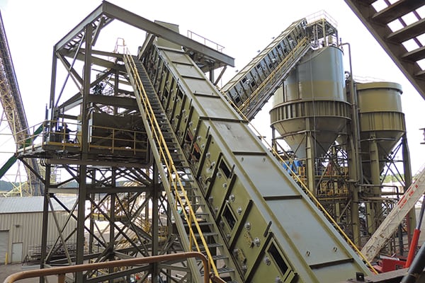
Xcel Energy’s Arapahoe Generating Station, located south of downtown Denver, is configured with a hydraulic bottom ash system that removes about 240 cubic yards of dewatered ash every 10 to 14 days. Dewatering bins were installed and commissioned approximately six years ago to reduce water consumption and the amount of waste material. After dewatering, the mixture of the material discharged to the trucks is approximately half water, which means that the dewatering system also disposes about 1,000 gallons of water over the same time period. The plant’s original discharge pond remains in service.
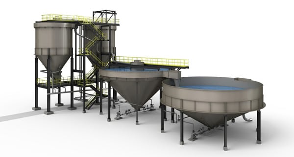
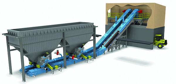
The dewatering system consists of two 100%-sized dewatering bins, each of which is 22 feet in diameter, 50 feet tall, and holds roughly 62,600 gallons. The dewatering bins receive water from several sources from within the plant: the bottom ash hopper overflow sump, recirculated water from the high-pressure bottom ash hoppers, surge and settling tank sludge return pumps, and the dewatering bin area sump. In short, any water entering the bottom ash–handling system will find its way to the dewatering bins (Figure 1).
 |
| 1. Dewatering system overview. A water–bottom ash mixture is sent to the bins to filter the water from the solids. The mixture is separated when it passes through screens located at the bottom of each bin. The recovered water is collected in the settling tanks before treatment and reuse. Courtesy: Nalco Co. |
Sluice water entering the dewatering bins provides sufficient residence time for the bottom ash to settle out. The water is first decanted from the dewatering bins and sent to an ~86,500-gallon settling tank to remove any remaining ash particles, which are returned to the dewatering bins by sludge return pumps. Next, the high–ash content mixture remaining in the dewatering bins is removed via screens located on the tank bottom and hauled away in trucks for disposal.
Water from the settling tank and any required makeup water is directed to an ~148,600-gallon surge tank. Closing the loop, water in the surge tank is the primary water source for the entire hydraulic bottom ash system and for housekeeping purposes, such as periodic flushing of the surge and settling tanks, dewatering bins, and the bottom ash overflow and dewatering bins sumps. As a backup, makeup water can also be collected from the discharge pond.
Surge tank water has two critical uses. First, a low-pressure (LP) water circuit is used to maintain the pressure seal on the boiler bottom ash system. The connection between the top of the bottom ash hopper and the bottom of the boiler seals in combustion gases and accommodates the vertical thermal expansion of the boiler (Figure 2). The pressure seal has two parts. A water trough is attached to the top of the fixed bottom ash hopper. Next, a skirt, located around a rectangular opening on the bottom of the boiler through which the bottom ash falls, remains continuously immersed in the 80F to 90F trough water as the boiler moves up and down due to thermal expansion and contraction. A loss of trough water will result in the loss of the boiler pressure seal, furnace pressure will drop, and a boiler trip soon follows. The second critical use is to cool the refractory on the bottom of the boiler.
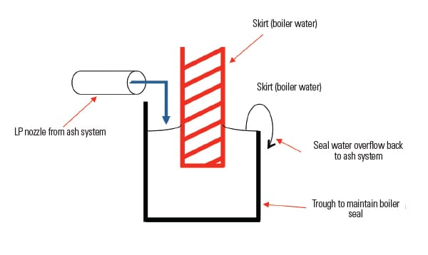 |
| 2. No way out. The seal water system keeps the combustion gases in the furnace while allowing ash to fall through a rectangular opening in the boiler bottom. The seal is a skirt around this opening that remains submerged in water as the boiler vertically expands and contracts during operation. Recycled water is used to maintain the seal. Source: Nalco Co. |
Water Woes
Since commissioning the ash system, the plant has struggled with two areas of plant operation. First, fouling of the piping and nozzles of the LP water circuit would reduce water flow that would cause either degradation or, in some cases, complete loss of the boiler pressure seal. When the seal is lost, city water must be used as a replacement. In addition to boiler operation issues, the cost of supplementing with city water is steep, and operators are pulled away from their normal work to manage the trough water levels (Figure 3). In the words of plant management, “[It is] a major headache for the plant, with the worst case scenario being plant shutdown.”
 |
| 3. Closed for business. The near complete obstruction in the seal water nozzle was due to scale formation. Periodic system outages to clean pipes and equipment were required. Courtesy: Nalco Co. |
Fouling of the center screen in the dewatering bins causes the second operational headache (Figure 4). When the screens become obstructed, excess water is entrained with the ash, thus prohibiting it by law from being transported on the highway due to excess water content. The logistics of removing bottom ash from the plant to the disposal area can get complicated, as the timing and number of trucks required to move the waste is limited. In the worse case, the inability to process bottom ash in a timely way can cause a plant forced outage. Finding a solution to the problem of pipes fouled with bottom ash was critical for the plant to maintain efficient plant operation.
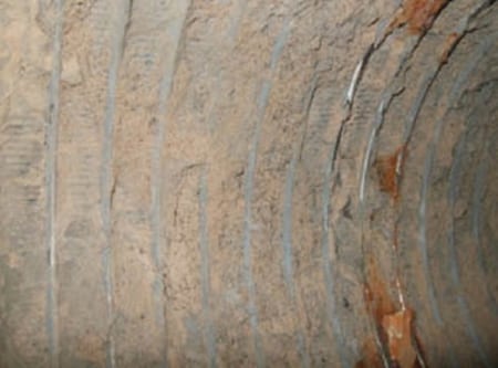 |
| 4. Sealed tight. At the bottom of each of the bins shown in Figure 1 is a series of screens that separate the ash from the sluice water. The water passes through the screens and is recycled, and the ash collects on the screens, as shown here. When operating correctly, the ash falls from the screens into a truck bed for disposal. The plant routinely experienced ash deposits that required manual cleaning of the screens. Courtesy: Nalco Co. |
The real cost incurred by the plant with these operational problems is significant. Based on conversations with plant personnel, the dewatering system and piping required cleaning with high-pressure water every two weeks at a cost of $3,000 to $5,000 per event. To ensure a thorough cleaning, the system also required disassembly, cleaning, and reassembly—a two-day process. In all, plant staff estimate that just fees paid to a contract cleaning company related to dewatering system fouling/scaling are around $120,000 each year. That estimate would be much higher if the plant staff hourly costs and the cost of any operational limitations, particularly a forced outage, were included.
Understand the Chemistry
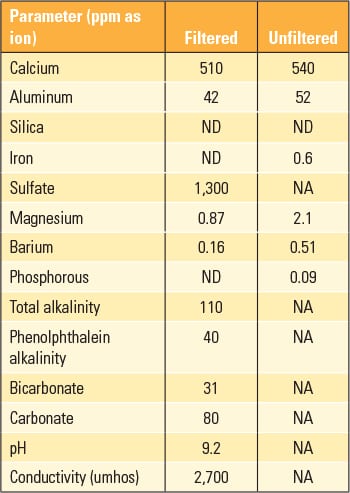
Analysis of the deposits found on the inner-diameter pipe walls found calcium carbonate and aluminum-hydroxide scale (Table 1). The deposit was fairly soft, probably due to the hydroxide present. Knowledge of the constituents of the scaling is an important factor when developing a trial treatment program.
 |
| Table 1. Deposit and scale analysis. Source: Nalco Co. |
Water chemistry experts examined the bottom ash sluice water chemical analyses (Table 2) and realized that minimizing fouling and scaling would be very difficult, particularly because the sluice water was relatively high in hardness given the pH of the water. The elevated pH, hardness (total dissolved solids, TDS), and total suspended solids (TSS) of the water made for a difficult selection of the proper scale inhibitor and solids dispersant. Furthermore, recall that the bottom ash loop is essentially closed with very little water loss or makeup, so any water chemistry program selected must also remain stable for extended holding times.
 |
| Table 2. Bottom ash water analysis. Source: Nalco Co. |
Based the operating conditions of the system, a chemical additive (Nalco 5200m) was selected because it is excellent in minimizing calcium carbonate scaling as well as minimizing the potential for fouling due to aluminum and particulate matter. Once the chemistry selection was made, the volume of water in the system, water losses, and makeup source quality had to be found in order to develop the correct dosage rate. However, the makeup to the ash-handling system is usually discharge pond water, which consists of myriad sources, ranging from river water to floor drains and cooling tower blowdown. There is no metering on the makeup to the ash system, so determining water loses was difficult.
The decision was made to base the additive feed rate on the total volume of the system for initial dosage purposes and then maintain chemical feed of 20 ppm of product, based on organic-phosphate residuals. Based on tank capacities, the total ash-handling system volume was determined to be roughly 330,000 gallons. This is based on the tank capacities plus 20% for piping and the many sumps throughout the system.
The best location for injecting the additive was determined to be the LP header, and a hot tap at this location was easily completed. This location was also ideal because the LP circuit was of most concern, and feeding the scale inhibitor there would be appropriate from a chemical demand perspective (Figure 5).
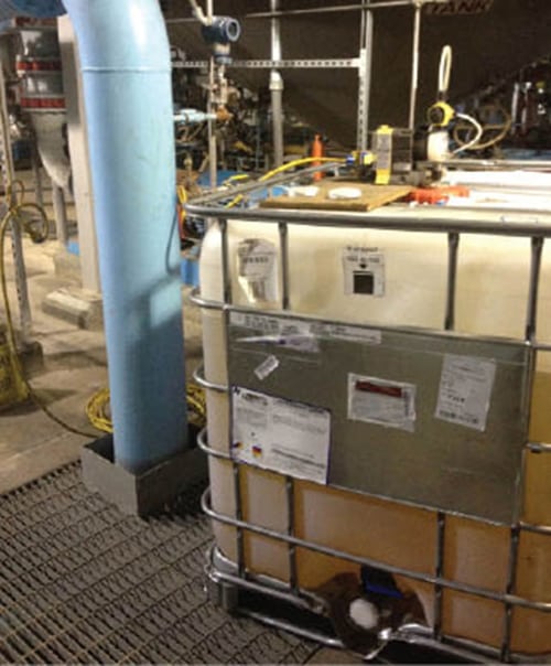 |
| 5. Feeding tube. The hot tap for the chemical injection portion is shown on the blue pipe. The Nalco 5200m is fed directly from the chemical tote. Courtesy: Nalco Co. |
The metric used to determine the success of the trial was scale formation on the seal water nozzles and center screens. The plant arranged for a complete cleaning of the entire dewatering system (at a cost of about $50,000) prior to the start of the trial. Once cleaned, plant staff monitored scale formation and fouling by performing visual inspections of the nozzles and center screens.
The trial began in August 2012, with no set end date established. If cleaning frequencies did not improve, the trial would be terminated. However, if the cleaning frequencies decreased, the trial would continue so that a proper economic analysis could be performed. If the reduced cleaning frequency justified the cost of the chemical treatment regimen, then the trial run would become a permanent solution.
Squeaky Clean Results
One year has elapsed since the start of the trial, and dewatering system, center screens, and seal water nozzles still do not require pressure washing. Keeping the system clean required, on average over the year, only 2.3 gallons per day of scale inhibitor. The economics of the trial were straightforward: The prior cleaning costs were approximately $120,000 per year, and the cost of chemicals was about $20,000 per year, producing a simple payback of about two months. This simplistic analysis ignores the time spent by plant staff performing housekeeping chores and the very high cost of plant downtime.
Perhaps as important as the monetary savings was a grateful O&M staff released from unproductive housekeeping chores to resume the jobs for which they were trained. ■
—Kevin Boudreaux is a power industry technical consultant for Nalco Co.’s Power Group.