Modern equipment can be sensitive to brief disturbances on utility power mains. Electrical systems are subject to a wide variety of power quality problems that can interrupt production processes, affect sensitive equipment, and cause downtime, scrap, and capacity losses. The most common disturbance, by far, is a sag: a brief reduction in voltage lasting a few hundred milliseconds.
Sags are commonly caused by fuse or breaker operation, motor starting, or capacitor switching, but they are also triggered by short circuits on the power distribution system caused by such events as snakes slithering across insulators, trenching machines hitting underground cables, and lightning ionizing the air around high-voltage lines. Many utilities report that 80% of electrical disturbances originate within the user’s facility.
A decade ago, the solution to voltage sags was to try to fix them by storing enough energy somehow and releasing it onto the AC mains when voltage dropped. Some of the old solutions included an uninterruptible power supply (UPS), flywheels, and ferroresonant transformers.
More recently, engineers have realized that voltage sag is really a compatibility problem with at least two classes of solutions: You can improve the power or you can make the equipment tougher. The latter approach is called “voltage sag immunity,” and equipment manufacturers have several compliance standards that you should be aware of when specifying future equipment purchases (Figure 1).
|
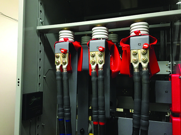
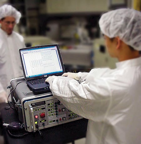
1. Immunize your plant. Voltage sag immunity testing has been common in the semiconductor industry for years and has proved its economic value. New IEC standards for voltage sag immunity will expand this kind of testing and certification to other industries. Courtesy: Power Standard Labs
|
Standards developed
Three main primary voltage sag immunity standards are discussed in the following paragraphs: IEC 61000-4-11, IEC 61000-4-34, and SEMI F47. There are others in use—such as IEEE 1100, CBEMA, ITIC, Samsung Power Vaccine, international standards, and MIL-STD—but the first three seem to have the widest acceptance in the marketplace. (IEC is the International Electrotechnical Commission, SEMI is the Semiconductor Equipment and Materials Institute, CBEMA is the Computer Business Equipment Manufacturers Association, ITIC is the Information Technology Institute Council, and MIL-STD is the U.S. Defense Department’s specification.)
IEC 61000-4-11 and IEC 61000-4-34 are a closely related set of standards that cover voltage sag immunity. IEC 61000-4-11 Ed. 2 covers equipment rated at 16 amps per phase or less while IEC 61000-4-34 Ed. 1 covers equipment rated at more than 16 amps per phase. The latter was written after IEC 61000-4-11, so it seems to be more comprehensive.
SEMI F47 is the voltage sag immunity standard used in the semiconductor manufacturing industry, where a single voltage sag can result in the multi-million-dollar loss of product if a facility is not properly protected. The semiconductor industry has developed specifications for its manufacturing equipment and for components and subsystems in that equipment. Enforcement is entirely customer-driven in this industry, as semiconductor manufacturers understand the economic consequences of sag-induced failures and generally refuse to purchase new equipment that fails the SEMI F47 immunity requirement. SEMI F47 is currently going through its five-year revision and update cycle.
All three standards specify voltage sags with certain depths and durations for the equipment under test (EUT). For example, a specification may state 70% of nominal for 500 milliseconds. The percentage is the amount of voltage remaining, not the amount that is missing. Each standard specifies pass-fail criteria for EUT when a voltage sag is applied; the IEC standards have a range of pass-fail criteria, but the SEMI F47 standard is more explicit (Figure 2).
|
2. Playing through. A typical example of a voltage sag ride-through curve compared with the SEMI F47 specification commonly used in the semiconductor industry. Source: Power Standard Labs
|
Three-phase testing
For three-phase EUT, the sags are applied between each pair of power conductors, one pair at a time. If there is a neutral conductor, this implies that there are six different sags at each depth-duration pair: three different phase-to-phase sags and three different phase-to-neutral sags. If there is no neutral conductor, there are just three different phase-to-phase sags at each depth-duration pair in the standard.
Note that IEC 61000-4-11 and 61000-4-34 specifically forbid creating phase-to-phase sags by sagging two phase-to-neutral voltages simultaneously—an approach that is permitted in SEMI F47. Instead, you must create phase shifts during your phase-to-phase sags—something that sag generators designed for these standards do automatically (Figure 3). Typical suppliers of compliant sag generators include Keytek (www.keytek.com), Power Standards Lab (PSL, www.powerstandards.com), and Schaffner (www.schaffner.com).
|
3. One phase at a time. The IEC standards require phase shifting during sags on three-phase systems, but sags on all three phases simultaneously are not required. Source: Power Standard Labs
|
Test equipment required
A voltage sag generator is test equipment that is inserted between the AC mains and the EUT. It generates voltage sags of any required depth and duration. Some, like the PSL Industrial Power Corruptor, include preprogrammed sags for all of the IEC, SEMI, or MIL standards.
Because a common EUT failure mechanism is a blown fuse or circuit breaker during the current inrush after a voltage sag, the sag generator must be specified for delivering large peak currents—typically in the hundreds of amps. This peak current requirement in the IEC standards means that electronic amplifier AC sources generally can only be used for precompliance testing, not for certification (Figure 4).
|
4. Portable power. Portable voltage sag generators like this Industrial Power Corruptor from Power Standards Lab handle hundreds of amps at three-phase voltages while remaining portable. Built-in standards help speed up testing; built-in digital oscilloscopes help the test engineer diagnose equipment problems. Courtesy: Power Standard Labs
|
The portability of sag generators is a key consideration. It is often impossible to bring larger room-sized industrial equipment to a test lab. Instead, the test lab must travel to the equipment. In general, the largest portable sag generators can handle no more than 200 amps per phase at 480 volts (Figure 5). Some of the standards, such as SEMI F47, offer specific advice about how to test EUT that require more than 200 amps (usually by breaking them down into subsystems).
|
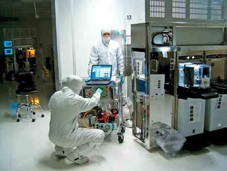
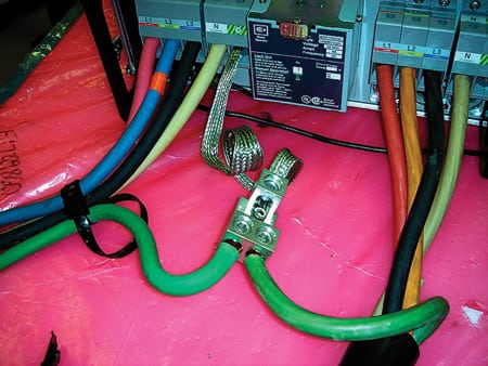
5. Potential for problems. The voltage sag test engineer will insert a sag generator between the AC source and the equipment being tested. Often, high currents (200 amps) and high voltages (480 volts three-phase) must be handled. Courtesy: Power Standard Labs
|
Many conformance certification labs subcontract voltage sag testing to labs that have engineers with the training and experience both to perform sag testing and to help diagnose EUT failures. This is an especially attractive approach when certifying large, industrial loads.
For testing smaller commercial and industrial loads, many labs rent a voltage sag generator from PSL or another supplier. Such a rental often comes complete with over-the-phone engineering support from an experienced sag testing engineer. This can be the best way to get started on voltage sag immunity testing.
A different kind of testing
In contrast to most other emissions and immunity testing, votage sag testing requires the engineer to control and manipulate all of the power flowing into the EUT. For smaller devices such as personal computers, this is not a great challenge. But for larger industrial equipment, perhaps rated at 480 volts three-phase at 200 amps per phase, with an expected inrush current of 600 amps or more, the test engineer must be prepared for serious performance and safety challenges.
Certain software, such as the sag immunity testing software from PSL, comes with extensive safety checklists. Some of the checklist items are obvious (Who on the test team is trained in CPR? Where is the closest fire extinguisher?), but some are less obvious (How do we get access to at least two upstream circuit breakers? Where is the closest trash can?).
Common failure mechanisms
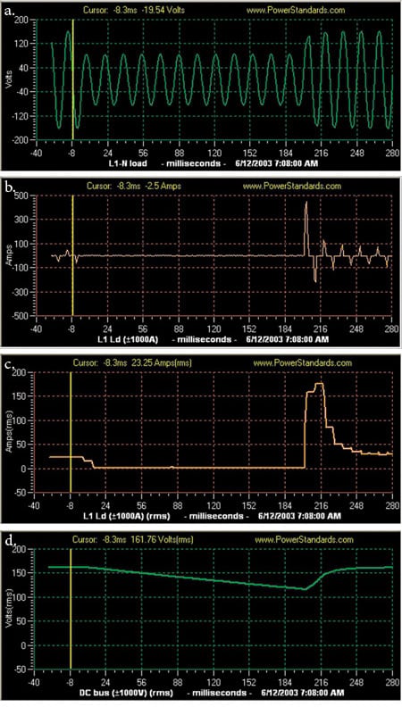
The most common failure mechanism is lack of energy. This can manifest itself in something as simple as insufficient voltage to keep a critical relay or contactor energized or something as complex as an electronic sensor with a failing power supply giving an incorrect reading, which would cause EUT software to react inappropriately (Figure 6).
|
6. Anatomy of voltage sag. To test a new device, a voltage sag is introduced in the power source (a). The waveform, which was about 40 amps peak before the sag in this example, then increases to 450 amps peak after the voltage sag (b). The same current, this time expressed as an RMS value, is shown. The next graph shows the same current, this time as an RMS value. Before the sag, it was about 23 amps RMS (this equipment was rated at 30 amps), but after the sag the current increased to 175 amps RMS. This behavior is not unusual (c). The final graph shows the output of a DC supply during this sag (d). Courtesy: Power Standard Labs
|
The second most common failure mechanism, surprisingly, occurs just after the sag has finished. In such cases, all of the bulk capacitors inside the EUT recharge at once, causing a large increase in AC mains current. This increase can trip circuit breakers, open fuses, and even destroy solid-state rectifiers. Most design engineers correctly protect against this inrush current during power cycling, but many do not consider the similar effects of voltage sags. Be careful when the test procedure is developed; if you use a sag generator that lacks sufficient current capability it will incorrectly pass the equipment if there is insufficient current available to blow a fuse or trip a circuit breaker in a half-cycle.
Another common EUT failure mechanism occurs when a sensor detects the voltage sag and decides to shut down the EUT. In a straightforward example, a three-phase EUT might have a phase-rotation relay that incorrectly interprets an unbalanced voltage sag as a phase reversal and therefore shuts down the EUT. A more atypical example would be if you had an airflow sensor mounted near a fan, it detected that the fan had slowed down momentarily, and the equipment software misinterpreted the message from this sensor as indicating that the EUT cooling system had failed. In this case, a software fan failure signal delay is the solution to improve sag immunity.
Another common EUT failure mechanism involves an uncommon sequence of events. For example, in one case, a voltage sag was applied to the EUT and its main contactor opened with a bang. But further investigation revealed that a small relay, wired in series with the main contactor coil, actually opened because it received an open relay contact from a stray water sensor. That sensor, in turn, opened because its small 24-VDC supply output dropped to 18 V during the sag. The solution was an inexpensive bulk capacitor across the 24-VDC supply.
Many other failure mechanisms can take place during voltage sags. The question to the test engineer will always be: How do we fix this problem? Usually, there is a simple, low-cost fix once the problem is identified.
Protect your equipment
There is no one best place to locate a protective device for all your plant equipment. An equipment protection program should begin with identifying specific equipment items that are sensitive to voltage sags, either through hard experience or with the support of the manufacturer. The ubiquitous UPS may not provide enough of the right protection.
However, there are areas where voltage sags have a history of interfering with plant operations by affecting programmable logic controllers as well as relays and contactors in sensitive equipment. The best approach to handling those problems is to specify new equipment according to a particular voltage ride-through specification, such as SEMI F47.
If you have recently upgraded to adjustable-speed drives (ASDs) in your plant, you are in luck. ASDs can ride through voltage sags because of the inertia of the motor and the connected load. Some ASD manufacturers offer an optional voltage sag ride-through feature.
Very short sags can be tolerated with ferroresonant transformers, magnetic synthesizers, or active series compensators. Others have employed static transfer switches and fast transfer switches that can operate within two cycles to protect overly sensitive loads.
At PSL, we believe that only in extreme cases should devices that eliminate voltage sags on the AC circuit be considered because this is the most expensive possible solution. However, the final selection of a solution requires weighing the cost of equipment and production losses against the cost of protection.
—Andreas Eberhard (aeberhard@powerstandards.com) is vice president of technical services for Power Standard Labs.