A conventional coal plant’s CO2 emissions can be reduced either after combustion (see Part I of this article in POWER, June 2008) or before. In the latter case, typified by integrated gasification combined-cycle (IGCC) plants, the fuel used is synthesis gas (syngas), which contains mostly hydrogen (H2) and CO. A water-shift reactor converts the CO to CO2, which is then removed by physical absorption. The H2 in the syngas is used to fuel one or more gas turbines.
Because this approach is substantially different (it requires replacing the plant’s coal-fired boiler with combustion turbines), we will not discuss it further here. Instead, we will concentrate on other possible methods of CO2 reduction.
Oxyfuel combustion
Among those methods is oxyfuel combustion. Burning coal in the presence of oxygen, rather than air, produces a highly pure CO2 exhaust that can be captured and sequestered at relatively low cost. Often, the oxygen is mixed with the exhaust to regulate combustion and to raise the level of CO2 in the flue gas.
In the Rankine steam cycle with oxyfuel combustion, the volume of flue gas leaving the boiler is considerably smaller than the volume of air entering it. Why? The large amount of N2 in combustion air (78%) does not become part of the flue gas. As a result, the volume of flue gas from an oxyfueled plant is about 75% lower than that from a plant using air for combustion. The flue gas from an oxyfueled plant consists primarily of CO2. Figure 1 shows a block diagram of a typical oxyfuel process, and Table 1 highlights its advantages and limitations.
1. A typical oxyfuel combustion block diagram. Source: Bechtel Power Corp.

Table 1. Oxyfuel combustion’s pluses and minuses. Source: Bechtel Power Corp.
Theoretical and experimental research into this technology has intensified over the past two years. Several pilot plants are now operating in the U.S., Germany, and Japan.
At the heart of the oxyfuel process is an air separation unit (ASU), a large vessel that consumes much electricity. In an effort to reduce its load and penalty on plant output, new, more energy-efficient oxygen separation technologies are in development. They include ion transport and oxygen transport membranes and BOC Group’s ceramic autothermal recovery process for oxygen production.
Air-fired combustion has better thermal performance than oxyfueled combustion, as Table 2 shows. Although the level of unburned carbon in both processes’ flyash is similar, more coal needs to be burned in oxyfuel combustion to achieve the same net output.
Table 2. Oxyfuel combustion’s thermal performance. Source: Bechtel Power Corp.
Oxyfuel with postcombustion carbon capture system
As with the other carbon capture and sequestration (CCS) options, proximity to an active CO2 sequestration site will surely become a requirement for the oxyfuel option in the future. The distance from a geological storage place or an enhanced oil-recovery site influences not only the plant’s economics but also its configuration and auxiliary power requirements.
Compared to a conventional coal-fired plant, an oxyfuel plant requires a number of new components besides the CO2 capture hardware. Examples include an ASU, additional flue gas treatment modules, several heat exchangers to extract low-grade heat, and fans and ducts for flue gas recirculation (FGR). The optimal FGR ratio is still a topic of investigation.
Adequate space must be allocated not only for the equipment but also for the interconnecting pipes, electrical cables, and controls. While SO2 and other elements can be removed in the CO2 capture plant, the quality of recirculation flue gas must be controlled in supplementary or modified sulfur-removal devices to avoid long-term corrosion of the boiler.
Another aspect to be considered is the increased cooling duty of the plant required by the ASU, flue gas condenser, and CO2 compression unit. When the heat sink is a cooling tower, the plant layout needs to account for additional cells capable of coping with a larger cooling load than a conventional plant without CCS. The issue of water will only become more contentious in the future siting of all power generation facilities; it could be even more critical with plants employing CCS. (See “New coal plant technologies will demand more water,” POWER, April 2008.)
In principle, the steam turbine configuration for this CCS option is the same as for a conventional steam plant without carbon capture. However, the cycle energy balance indicates that low-grade heat from several sources, such as the ASU and the CO2 compressor, could be recovered, allowing substantial reduction in bleed flows for condensate and feedwater heating. As a result, there would be an increased low-pressure (LP) flow through the turbine. If the LP module last-stage blade system and generator are sized properly to handle the additional flow, the steam turbine gross power output increases. According to one original equipment manufacturer (OEM), the gross power output could be increased by as much as 4.5% or more. This arrangement also yields better efficiency. Some LP steam extractions are required for oxygen preheating and the ASU plant dryers.
Cofiring biomass
Biomass fuel is considered “CO2 neutral” because its emissions of CO2 from combustion are offset by the absorption of CO2 from the atmosphere during plant photosynthesis. Therefore, one should consider cofiring biomass fuel in pulverized coal (PC)-fired electric utility boilers for the purpose of potentially achieving a net reduction of CO2 emissions per MWh. (See “Experts ponder future of biomass industry” in POWER, May 2007 for more discussion of biomass CO2 tradeoffs.)
Biomass fuels available for cofiring with coal include waste materials and energy crops. Waste products include wood wastes (such as wooden pallets, sawdust, and manufacturing scraps) as well as solid wastes or sludge. Agricultural wastes may include corn stalks, rice hulls, and straws (from oats, wheat, alfalfa, and barley). Energy crops include fast-growing switchgrass and trees such as poplar and willow.
Most of the design challenges to boiler operation when cofiring biomass derive from fuel properties. Coal and biomass can be very different fuels in terms of composition, in particular their inorganic content. In general, biomass usually creates less ash than coal, and the composition of its ash tends to reflect the inorganic material required for plant growth. When considering the use of biomass, also be sure to remember that biomass has lower bulk density and higher moisture content than coal. Thermal decomposition starts earlier for biomass, biomass has more oxygen than coal, and it is typically more porous and reactive.
These differences imply that a high percentage of biomass fuels blended with coal may lead to increased rates of deposit formation, which would require more frequent sootblowing, increase the risk of corroding heat transfer surfaces, and lead to higher flue gas temperature. The magnitude of these implications depends on the quality of the biomass and can be mitigated by limiting the amount of biomass in the fuel blend to 10% or less. This approach represents the least risk to normal boiler operation and material-handling system capacity for cofiring biomass in existing plants.
Switchgrass is one of the promising biomass fuels due to the following favorable features: its native origin in North America, adaptation to an extremely wide range of climates and soil types, effectiveness in CO2 absorption, and rapid establishment compared to that of woody crops. However, the land area needed for planting switchgrass for continuous 10% cofiring of biomass varies widely, depending on switchgrass yield per acre. And storage requirements are huge for a 365-day supply of biomass energy crop. In most cases, the economics of growing energy crops may require subsidies from the federal or state governments.
In designing a biomass fuel-handling system, several options should be considered.
If the proportion of biofuel is rather low (3% to 5% by weight), it may be fed together with coal to coal mills and then burned together with coal through coal burners. In principle, this option has the lowest capital cost and requires the lowest upfront investment.
A second option—separate handling, metering, and conveying of biomass via dedicated biomass transport pipes and injection into pulverized coal pipes downstream of the coal mills but either upstream of the burners or directly at the burners—requires installation of a number of biomass transport pipes.
Separate handling, control, and combustion of biomass through a number of dedicated burners presents the least risk to normal boiler operation and the highest capital cost investment. The use of dedicated burners/injectors for firing biomass fuel is highly advantageous when significant quantities of up to 10% biomass fuel are to be fired. This design has been successfully tested in the field for switchgrass biomass fuel.
Increased cycle efficiency
There is a linear relationship between cycle efficiency and CO2 emissions on a power output basis. Taking advantage of this relationship, another tool to reduce air pollutant emissions in general and CO2 in particular is to design more-efficient thermal cycles than are possible with the current generation of subcritical steam plants at supercritical (SC) and ultrasupercritical (USC) conditions.
To achieve better efficiencies, the boiler and steam turbines (STs) need to operate at substantially higher pressures and temperatures in the SC and USC domain. Though the definition of SC conditions is straightforward, the meaning of USC is subject to disagreement. To provide a clearer understanding, the three types of plants are defined below:
- SC is a cycle with a main steam temperature of less than 1,112F operating at pressures between 3,208 and 4,000 psia.
- USC is a cycle with a maximum steam temperature greater than 1,112F operating at pressures higher than 4,000 psia.
- Advanced USC is a thermal cycle with a steam temperature of 1,300F or greater.
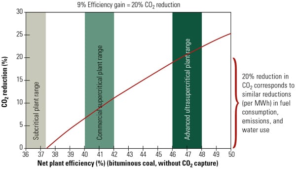
The major challenge facing OEMs is the availability of material capable of continuous operation at temperatures above 1,100F and pressures above 3,700 psia. To compete with alternative advanced coal combustion systems, such as IGCC, SC and USC plants must achieve net plant efficiencies greater than 40% (HHV) without significantly increasing the plant’s capital cost. The impact of the increased cycle efficiency on CO2 emissions can be seen in Figure 2.
2. Efficiency pays. This chart shows the relationship between cycle efficiency and CO2 reduction, using a standard subcritical plant as the baseline. Source: Bechtel Power Corp.
The high thermal efficiency of the SC and USC steam power plants cannot be achieved without the use of new alloys with higher creep strength and improved oxidation resistance. The most severe-service material science designs are with the SC and USC operating conditions found in boilers; however, significant design challenges remain with advanced steam turbines and interconnecting hardware such as main steam pipes, valves, and so on to handle these higher pressures and temperatures.
More than 20 units are in operation worldwide with main steam temperatures of 1,080F to 1,112F and pressures of 3,400 psi to 4,200 psi. Operation above 1,000F was possible due to the continuous development effort to improve the 9% to 12% ferritic steels (T91/P91, T92/P92, and T112/P122) as well as some advanced austenitic alloys (TP347, HFG, and Super 304). However, a major problem associated with the use of P91/P92 materials is the need for quality control at manufacturing facilities. In project execution, the quality of welding and postwelding treatments, particularly in the field, continues to be a concern, requiring that the treatments be monitored closely. The future will, without a doubt, lead to increased use of USC technologies. (See “Why new U.S. supercritical units should consider T/P92 piping,” POWER, April 2006.)
Renewable options abound
Renewable power technologies have matured and are capable of replacing significant amounts of oil-, gas-, and coal-fired generation. In particular, wind energy has become the clear leader (ignoring existing hydroelectric projects) of large-scale renewable power generation. There’s now more than 20 GW installed capability, 5,224 MW of that brought on-line in 2007 alone. Solar photovoltaic, and in particular concentrated solar thermal (tower and trough) technologies, are being deployed in “utility-scale” projects in the 100- MW to 400-MW range.
It’s only natural to consider renewable resources either in stand-alone or hybrid configuration as another CO2 reduction technology. The dramatic impact of how much CO2 can be displaced by using renewables is illustrated in Table 3. For each MW of solar or wind power used to offset new fossil-fired generation, approximately 1 ton per hour of CO2 emissions is avoided.
Table 3. CO2 emissions of various energy conversion processes. Source: Bechtel Power Corp.
One particular form of renewable energy technology integrated with a convention power system is the hybrid plant. In a typical hybrid configuration, the steam generated by a solar power tower is supplied to a nearby coal-fired facility, rather than being used in a dedicated steam turbine to produce electricity. Such arrangements are particularly suitable for states where the solar energy is abundant and space is available. A modern Solar Tower, such as the SEGS plants built in the California desert in the 1980s, can produce steam at 2,400 psia and 1,000F conditions. In addition to the CO2 credit for the solar heat input, significant cost savings can be obtained in a hybrid arrangement. A stand-alone solar plant will require its own steam turbine and heat sink, whereas in the hybrid case these components are part of the main coal-fired facility (Figure 3).
3. Hybrid solar and coal-fired plant schematic. A hybrid plant, where 150 MW thermal (10% of the total plant heat input) is provided by a solar trough system is illustrated. The superheated steam at 865 psia and 650F is fed back into the cold reheat line of the coal-fired plant. Source: Bechtel Power Corp.
No silver bullet
A variety of alternatives for reducing CO2 emissions from power plants have been described. A plausible scenario for achieving future CO2 emissions reductions, or to demonstrate to permitting authorities that meaningful provisions are designed into the plant, may require a developer to implement several alternatives in concert.
For example, Figure 4 shows where the emissions of a coal-fired plant must be reduced from 2,071 lb CO2/MWh to the level of a natural gas-fired combined-cycle plant (1,200 lb CO2/MWh). In this case, from the available “tool box,” the following alternatives have being selected:
- Future CO2 capture for 20% of the flue gases stream. Cofiring with 10% biomass.
- Cycle efficiency improvement by 2 percentage points.
- Development of an on-site 100-MW wind farm.
- Buying CO2 credits at $20/CO2 ton.
4. Team approach to gas control. Here is how one set of options can reduce coal-fired plant CO2 emissions to the levels of a gas-fired combined-cycle plant. Source: Bechtel Power Corp.
Depending on the site conditions and the plant economics, different combinations can be created. The main point of the selection process is to choose alternatives that are considered “proven demonstrated technologies.” Because implementation of a CO2 reduction plan will occur after a plant is complete, the second consideration in the selection process is to identify options that are the least intrusive to the plant in terms of additional equipment, control, and the balance-of-plant’s ability to support the new additions.
—Dr. Justin Zachary (jzachary@bechtel.com) is senior principal engineer for Bechtel Power Corp., an ASME fellow, and a POWER contributing editor.