Technology advancements and new regulatory requirements could reshape how power plant owners operate and maintain large power transformers. Experts outline emerging strategies and call attention to overlooked components that could help prevent transformer failure.
Power transformers are arguably one of the most expensive and vital components in a power system. While they are typically reliable and relatively low-maintenance, sudden failures can result in the loss of power generation along with considerable costs and potentially wider implications for grid reliability.
According to SPX Transformer Solutions, a U.S. maker of medium and large power transformers, and which is also a transformer service solution provider, electrical disturbances are a leading cause of power transformer failure. An analysis it conducted of major failures between 1991 and 2010 (Figure 1) showed that phenomena such as switching surges, voltage spikes, line faults/flashovers, and other utility abnormalities are overwhelmingly responsible for transformer failures. Insulation, moisture, and foreign objects were also notable causes.
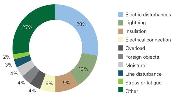 |
| 1. Causes of transformer failures between 1991 and 2010 (as a percentage of total failures). Source: SPX Transformer Solutions |
Advanced Diagnostics
According to Jim McIver, technology director at Siemens Transformers U.S., routine maintenance can help a transformer last up to 40 years and avoid most debilitating issues. But he also pointed to two emerging maintenance areas that could enhance performance and protect or extend transformer life: proactive actions and advanced diagnostics.
Advanced diagnostics involves service offerings by vendors to “more aggressively treat your transformers,” McIver said. “What you would really like is to be able to take some piece of complicated electronics out. Hook it up to the transformer. It does its measurements, and it comes back and it tells you, ‘This is what’s wrong with the transformer: This particular piece only has 1,000 more hours of service left in it. Go inside the tank and replace this particular component and avoid a failure.’ ”
Modern advanced diagnostics offerings include mechanical or electrical measurements taken from the outside of the transformer “to determine the state of the insides… without having to open it up and climb inside, because there’s a big cost involved if you have to de-energize the transformer, drain the oil, and open up all these sealed openings and have somebody try to crawl around inside.”
Partial discharge measurements, for example, offered by a number of companies including Siemens, allow assessment of the health of an insulation system using noninvasive measurement and analysis. Typically, the transformer is taken out of service and hooked up to a test-voltage source so that high-frequency partial discharge activity can be measured. Utilities would opt for additional testing like the partial discharge test if proactive monitoring indicates an issue, McIver said.
Other advanced diagnostic methods include frequency response analysis (FRA), which investigates the mechanical integrity of transformer windings. Generally, the test puts a low-voltage, high-frequency impulse into the transformer, and based on the “wave shapes” that are reflected back, an assessment can be made about “how the transformer windings are configured physically—how close together they are and how tall they are and what their diameter is, all of those things,” explained McIver. Another advanced diagnostic method is the dielectric frequency response test, which is an electrical test similar to the FRA to determine if the insulation is failing.
“It narrows down your source of investigation, and that’s good,” he said. “Any of these advanced diagnostics are trying to make a conclusion based off of something that you can measure externally. The risk is there that they don’t give you a real definitive result or they don’t specifically point to one particular area.”
However, advanced diagnostics are far from a conventional maintenance step. McIver noted: “There’s a lot of interesting things being proposed, but I don’t think the industry is really at a point where a lot of those things are generally being done to show payback.”
Transformer owners should more prudently focus efforts on routine maintenance—examining and changing out gaskets every three years and bushings per the manufacturer’s recommendations, for example—but also pay attention to proactive actions, such as condition-based maintenance, and especially monitoring.
Advances in Monitoring
Monitoring itself doesn’t change the behavior of the transformer, McIver noted. “The interesting part about that is in terms of industry philosophy. A lot of people pretty much just run transformers to the failure point. They’re very big, very expensive devices and, as they get older, there’s not a good financial justification to do dramatic changes to the device while it’s still in service.” So the monitoring really just gives owners a measure of the transformer’s health and tells them which parts to concentrate on and watch more closely.
Advances in monitoring include real-time sensors, which can deliver valuable results. One notable example is industrial measurement provider Vaisala’s real-time sensor for moisture in transformer insulation oil. An elevated moisture level in transformer oil is a widely recognized root cause of failures, because moisture essentially diminishes the ability of oil to act as an insulator.
Moisture content in solid insulation after initial factory drying is between 0.5% and 1%, depending on requirements, but it starts to increase gradually over the operating lifetime of the transformer. Vaisala said that one critical moisture source is residual moisture contained in thick structural cellulose components, which enters into transformer components from the air. Small amounts of moisture may also be generated as a byproduct of cellulose decomposition. In a power transformer, the majority of water is found in the solid paper insulation.
“Higher water content leads to accelerated deterioration of the paper, reducing its degree of polymerization,” the company said. “Moisture and heat provide an optimal environment for various compounds in the oil—such as acids and metal ions—to react with the cellulose molecules and break them down.”
When relative moisture saturation surges beyond 20%, the dielectric strength of oil starts to decrease rapidly, Vaisala said. Exceptional high-loading events could also drive excess moisture from the paper into the oil, creating relative moisture saturation of 100% and the formation of free water. That could increase the risk of corrosion and rust particles in oil circulation pipes and radiators, or worse, form around active parts, resulting in discharge that could cause catastrophic damage to the transformer.
“Traditionally, industry understanding of moisture dynamics in transformer oil has mainly been based on samples taken once annually that provide a limited ‘snapshot’ of oil health,” explained Steven Jiroutek, regional segment manager for industrial applications at Vaisala. “However, growing use of online moisture monitoring instruments in the global power sector means more utilities can access 24/7 streaming data to monitor the condition of their transformers. Integrating these instruments into a comprehensive monitoring system and analyzing real-time trends is enabling owners and managers to make better, more cost-effective maintenance and service decisions.”
Senja Leivo, a senior industry expert at Vaisala, told POWER that while moisture sensors have been on the market for nearly 20 years, Vaisala’s device, designed for installation directly into the oil circulation pipe of a transformer, was launched recently and has several installations globally. “If moisture levels are found to be too high, the transformer can be equipped with an online oil dryer or taken into more comprehensive offline overhaul,” she said.
Space Weather
One glaring cause of transformer failure is age. According to the Department of Energy’s Office of Electricity Delivery and Energy Reliability, the average age of large power transformers installed in the U.S. is between 38 and 40 years. The office said in an April 2014 report that more than 70% of the nation’s large power transformers are probably 25 years or older, noting there are some units well over 40 years old—and some even older than 70 years—that are still operating on the grid. The office worries that because more than 90% of consumed power passes through these large power transformers at some point, they are one of the most vulnerable components on the grid, faced with a wide range of potential threats including severe weather, space weather, and physical attacks.
In recent years, industry observers have raised alarms about geomagnetic disturbances (GMD), which occur when the sun ejects charged particles that interact with and cause changes in Earth’s magnetic fields. These charged particles can cause currents to enter the grid through long conductors.
According to Dom Corsi, a senior transformer engineer at Watertown, Mass.–based Doble Engineering Co., GMDs can essentially overheat a transformer’s internal component structure and affect actual current carry. “And the other thing that happens is, because these currents flow in the transformer and impact the transformer by producing a bias on the core, the transformer will saturate,” he told POWER in February. “During the saturation events, there’s a significant change in the transformer’s magnetizing characteristics (Figure 2), which causes it to draw reactive power from the grid. When the transformer draws reactive power from the grid, it can set up a system disturbance, which will lead to an instability. If you can’t compensate for the instability, then you have the probability of a cascading network event.”
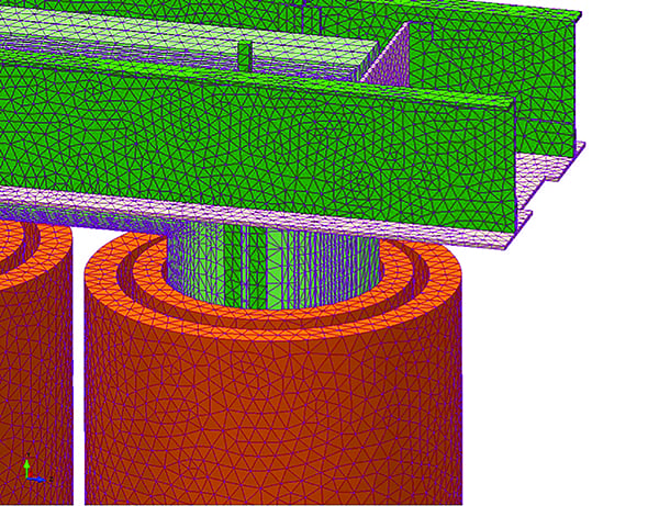 |
| 2. A magnetizing effect. Geomagnetic disturbances due to solar activity can lead to geomagnetically induced currents (GICs) in power system networks. These GICs are quasi-DC in nature (0.01 Hz to 0.5 Hz) and could saturate the core of a power transformer. The saturation of the core due to these currents may spur increased magnetizing currents, peaking beyond the nominal current of the unit. This image illustrates a sample exciting current magnetizing pulse due to GIC events. Courtesy: Trafoexperts |
Another impact is thermal, Corsi said. When the transformer saturates, the transformer flux spills out of the core. This affects the transformer in two different ways: “One is the additional main flux that spilled into the structural components and windings, creating additional heating. But also, because of the saturation, the harmonic content of this flux results in induced currents that also reach harmonics, which adds to the heating component.”
In 2012, Earth experienced a near miss by an extreme coronal mass ejection. Since then, several agencies have been exploring a number of grid resiliency solutions to counter the potential GMD threat. The Federal Energy Regulatory Commission (FERC) in September 2016 approved a reliability standard submitted in January 2015 by interstate grid security monitor North American Reliability Corp. (NERC) that, for the first time, establishes mandatory requirements for grid entities to guard against GMDs.
The standard, TPL-007-1, essentially applies to power transformers with windings on the high-voltage side that are connected at 200 kV or higher in a wye configuration and have a grounded neutral connection. Every 60 months, network planning coordinators and transmission planners must assess and report how vulnerable their system is to geomagnetically induced current (GIC) disturbances, and whether their system can withstand a “1-in-100-year” benchmark GMD event without causing a wide-area blackout, voltage collapse, or transformer damage.
Additionally, it requires that transmission owners and generators conduct a thermal impact assessment on their high-side, wye grounded transformers of more than 200 kV based on a maximum effective GIC value—which, according to the standard, is 75 amperes per phase or greater. If, per that assessment, these transformers cannot withstand thermal transient effects associated with the benchmark GMD event, transmission owners and generators must implement corrective action plans developed by coordinators and transmission planners.
Corsi noted that the timeline for NERC compliance kicked off on January 1, 2017. After network planners determine full GIC parameters as required by January 2019, transformers identified as vulnerable to GIC disturbances would need to complete thermal impact assessments by January 2021 (Table 1).
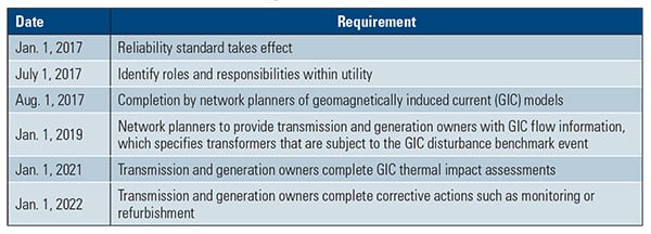 |
| Table 1. Significant deadlines for compliance with the North American Reliability Corp.’s “Transmission System Planned Performance for Geomagnetic Disturbance Events” reliability standard (TPL-007-1). Source: Doble Engineering |
Companies like Doble can help utilities meet the NERC standard by performing an engineering study on transformers older than 20 years (whose design review documentation may not be readily available) to establish power transformer capabilities while under GMDs, following guidelines established by the IEEE Standards Association, specifically, IEEE C57.163-2015. This guide specifies parameters and performance characteristics and evaluation techniques for power transformers to help minimize risks and impacts when GIC is present in the power system.
“Another component where Doble would contribute would be in the physical assessment of equipment,” Corsi said. “Although deadlines in [IEEE C57.163] have been established for group transformers, you also need to determine the physical condition of an H transformer, how it’s been loaded, how it’s aging, it’s physical condition as far as its ability to withstand the events. We also provide a lead up to the studies as far as determining the physical condition of the transformer, and maybe even how establishing thermal limits in order for the piece of equipment to withstand the GIC event,” he said.
Paul Griffin, vice president of Doble Professional Services, noted that while the NERC standard doesn’t require action for 24 to 36 months, some of Doble’s customers are looking to get ahead of the curve so that they fit into 12-month planning cycles, wanting to learn as far ahead to help with outage planning and budgeting processes. Another reason for early action is to leverage operational flexibility.
A Physical Approach
Physical threats to high-voltage transformers are another emerging worry that has engulfed transformer owners and legislators alike. Because they are behemoths—a typical 345-kV unit can weigh up to 435 tons—they are easily identifiable alongside power plants, or in network substations. Transformer experts assert that a bad actor with basic knowledge of transformer design could inflict irreparable damage. Such attacks can cause massive electrical short circuits and oil fires that would destroy a transformer and damage surrounding infrastructure.
The vulnerability of individual transformer substations was demonstrated most prominently by a rifle attack in April 2013 at Pacific Gas & Electric’s 500-kV substation in Metcalf, Calif., where multiple individuals reportedly shot at high-voltage transformer radiators with.30 caliber rounds, causing them to leak cooling oil, overheat, and become inoperative. In November 2014, FERC approved a NERC-submitted physical security reliability standard (CIP-014-1), which went into effect in January 2015. Essentially the standard requires transmission owners and operators to identify and protect substations and associated primary control centers. It calls on them to perform initial risk assessments to identify critical facilities, and to evaluate potential threats and vulnerabilities of a physical attack on those facilities by November 2016.
Operational measures that could make critical equipment more secure include reinforced perimeter fencing with opaque bulletproof walls, multiple fencing layers, and electronic motion sensors on fencing with multiple system triggers. Metalax’s expanded metal security fencing solution, for example, offers smaller openings, a rigid design, and ballistic resistance compared to typical chain-link fencing. Other measures include enhanced lighting systems and remote surveillance.
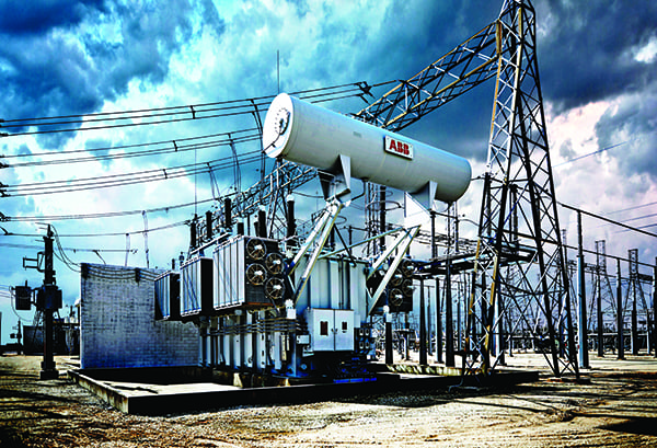
Zurich-based technology firm ABB also recommends equipment and substation hardening using cooling resiliency solutions and porcelain-free dry bushings (which it makes), which could eliminate the risk of explosion or fire. The company also recommends bullet-resistant technology. In November 2015, it rolled out its AssetShield ballistic protection solution (Figure 3), and it has since bagged three orders from major U.S. utilities for the impact and fragmentation-protective system designed for transformers, switchgear, circuit breakers, and capacitors. The solution’s optimized combination of coating and steel reduces the kinetic energy of the bullets and reduces spalling after impact, it said.
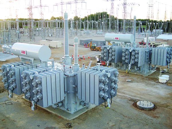 |
| 3. Transformer armor. Armor steel shielding of transformers and power equipment is part of the “hardening” process to provide components with advanced ballistic-level protection against physical attack. ABB’s AssetShield solution is designed to safeguard and protect large power transformers and other substation equipment. Courtesy: ABB |
The company also noted many transformer components can be fortified using the AssetShield system, including: tap changers, control cabinets, relays, oil-level indicators, valves, entry points, gas collection relays, temperature indicators, oil expansion systems, nitrogen systems, rapid pressure relays, gas monitors, silica gel breathers, and current transformers. ABB has also developed a transformer ballistic impact sensor, which can alert operators following a ballistic impact close to the transformer. Yet another solution offered by the company to protect transformers involves automated cooling valves, which can open and close based on an ABB-developed radiator/cooler leakage detection system.
Smart Predictive Maintenance
More utilities are also increasingly using the Industrial Internet of Things (IIoT) and analytics to improve transformer longevity, reduce maintenance costs, and ultimately, ensure critical assets have near-zero unplanned downtime.
In 2010, Duke Energy suffered months of lost power generation and debilitating losses of more than $10 million following a transformer failure that cascaded into other transformers and two turbines. The company had previously relied on manual programs to assess equipment health, said Bernie Cook, who is director of maintenance and diagnostics for central engineering at Duke Energy. “We knew that transformer had some issues, but we thought it had some life left. We’d review the health of these things every six months. Between those six months, we had a couple of bus issues that pushed the transformer over the edge, so we needed that online continuous monitoring.”
That’s why Duke Energy moved to implement SmartGen, a seven-year program (2012–2018) that combines sensors, microprocessors, data acquisition, data storage, and software. The program, which applies IIoT for predictive maintenance to its power generating fleet via four monitoring stations, has resulted in 384 finds during three years and conservatively avoided $31.5 million in repair costs.
A number of companies offer similar solutions. Doble offers an asset risk management system, dobleARMS. “It allows you to collect all the data from various sensors, offline data, laboratories, bring it all into one place, and have automated diagnostics, automated evaluation, and you can put in different criteria and things, and look at expense financial information, environmental information, environmental sensitivity,” explained Doble’s Corsi.
“But the idea is that today people want to understand the condition of the grid all the time, and getting closer and closer to really wanting to know within real-time. And so you need systems to be able to do that.” ■
—Sonal Patel is a POWER associate editor.