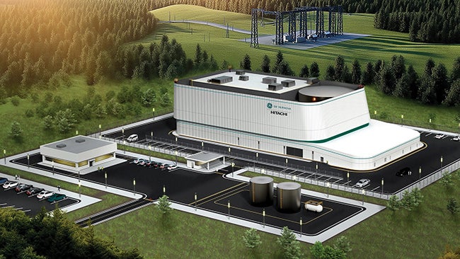
The Asheville Plant, owned by Progress Energy, consists of four units that produce 700 MW near Arden, North Carolina (Figure 1). Unit 2 is a Babcock & Wilcox front-fired reheat boiler with a maximum continuous rating (MCR) steam flow of 1,378 klb/hr at 1,985 psi and 1,000F. Reheat MCR is 1,224 klb/hr at 473 psi and 1,000F. The unit’s fuel-burning equipment consists of four EL-76 pulverizers, each supplying coal to a row of four burners. The boiler was built as a pressurized unit and was operated in that mode until a balanced draft conversion in 2007. A wet flue gas desulfurization (wFGD) system and selective catalytic reduction system were installed at the same time (Figure 2).
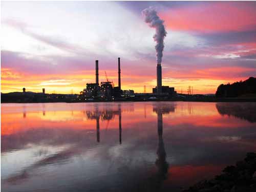
1. Progress Energy’s Asheville Plant. Courtesy: Progress Energy
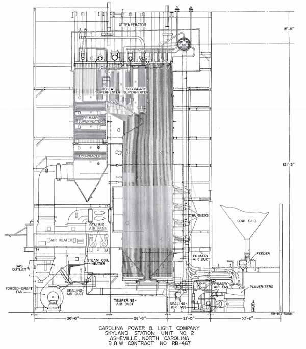
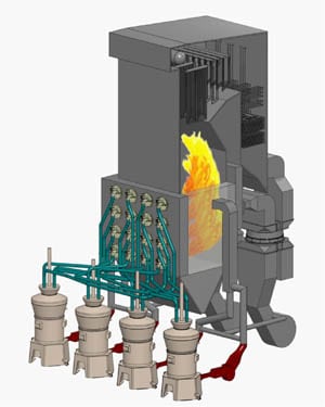
2. Boiler cutaway of the Asheville Plant’s Unit 2. Source: Progress Energy
Asheville Unit 1 was the first coal-fired unit modified with an FGD (November 2005) to meet the state’s Clean Smokestacks Act, which requires at least 97% of the SO2 to be removed from the stack gas. The FGD on Unit 2 was commissioned soon after Unit 1’s (May 2006).
Tube Leak and Combustion Study
In August 2007, the west region general manager commissioned two teams to investigate the increase in tube leaks that had led to forced outages at the Asheville Plant. One team was to study the cause and location of the tube leaks; the other team was to study combustion and its potential contribution to the tube leaks. The combustion team reviewed data and tested pulverizers for clean and dirty air distribution as well as fineness. Additional testing involved furnace high-velocity thermocouple (HVT) traverses.
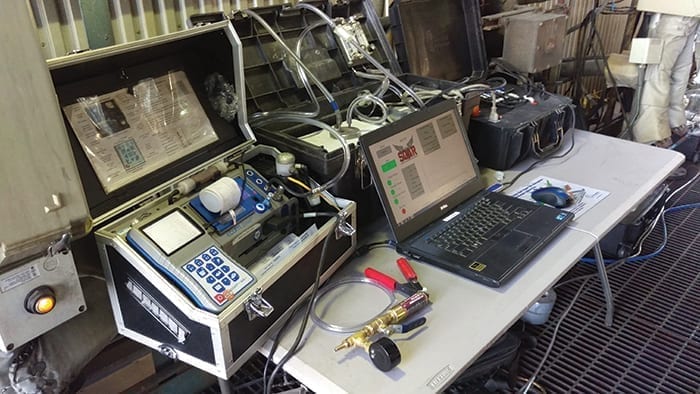
HVT testing is a labor-intensive and difficult task. Asheville’s Unit 1 has only a few locations in which the 20-foot HVT probe can be safely inserted. The HVT probe was inserted into two observation doors located on the front wall. The probe was fully extended (~16 feet) with measurements taken every 2 feet as the probe was withdrawn. Temperature, O2, and CO were recorded. Table 1 summarizes the data recorded during this test. The data illustrate that there were areas of the furnace with very little O2 and high levels of CO. Table 2 illustrates the overall averages of the data collected for the entire furnace. Testing was conducted at full load under the operating conditions defined in Table 3.
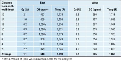
Table 1. As-found HVT results of data taken from Asheville Plant, Unit 2. Source: Progress Energy

Table 2. Overall average of as-found HVT results of data found in Table 1. Source: Progress Energy
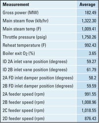
Table 3. Full load operating conditions of Asheville Unit 2 when the HVT data found in Table 1 were collected. Source: Progress Energy
Continuous Combustion Management (CCM) Project Begins
During the spring of 2008 the Continuous Combustion Management (CCM) project was developed to mitigate the low-oxygen and high-CO conditions in the furnace found by the boiler combustion study and the poor HVT results.
Progress Energy has had positive experience in installing CCM equipment at other boilers in the system. CCM consists of real-time online coal flow and burner secondary airflow, overfire airflow, and distributed control system (DCS) programming for closed loop control. Simply stated, air/fuel ratios are calculated using the individual burner airflow measurements (IBAMs) and coal flows. The average is used as a global air/fuel ratio setpoint. In closed loop control the individual air registers modulate to maintain a constant balanced air/fuel ratio at each burner. Additional upgrades at Asheville include new primary air (PA) flow elements, coal flow balancing valves, extractive CO analyzers, and the addition of two O2 analyzers for a total of four.
In addition, the CCM project modified the DCS to allow control of mass flow of air to each overfire air port as well as air/fuel ratio control of each burner. This was accomplished by utilizing the burner secondary air disks to control burner air and by controlling the coal to the burners. Also, PA measurement and control was improved to allow for better combustion. Coal velocity measurement from the continuous coal flow measurement systems was used to determine ideal primary air to feeder ratios in an effort to improve overall control.
All of the data collected from these new instruments was added to the OSIsoft’s PI data historian. This data is available from any computer in the system and allows for remote monitoring by central engineers, who may not always be at the plant. Each of the specific equipment selections is discussed in more detail below.
Airflow Monitoring. Progress Energy had previously selected Air Monitor’s PfFLO as its standard for real-time coal mass flow measurement. Coal measurement was installed on all 16 coal pipes (Figure 3).
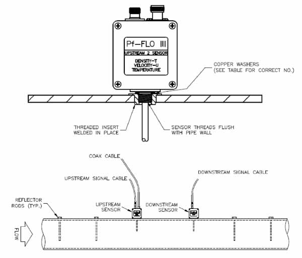
3. Air Monitor’s PfFLO. Source: Progress Energy
Secondary Burner Airflow and OFA Flow. Air Monitor’s secondary airflow devices (IBAM) were installed in each of the 16 burners. Wind tunnel testing of a full-scale model was conducted to establish accurate airflow measurements for each inner and outer swirl vane setting combination. Overfire air (OFA) IBAMs were installed in the six rear wall overfire air assemblies. The OFA registers were wind tunnel tested in the same manner as the burners (Figure 4).
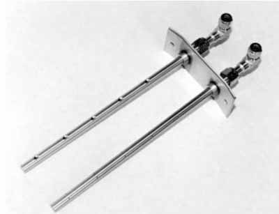
4. IBAM probe for wall-fired applications. Courtesy: Progress Energy
Primary Airflow Monitoring. Asheville Unit 2 was converted from forced draft operation to balanced draft in 2006. As a result, the existing PA flow venturis at the inlet of the individual PA fans were unreliable. New Air Monitor PA flow pitot tubes and transmitters were installed at the PA fan discharge (Figure 5).

5. New monitor primary air pitot tube and transmitter. Courtesy: Progress Energy
Coal Flow-Balancing Valves. Coal flow balancing valves supplied by Combustion Technologies were installed in the coal pipes as close to the mill discharge as physically possible. The valves are a perforated/butterfly style that promote coal particle control and dispersion without unnecessarily restricting primary air (Figure 6).
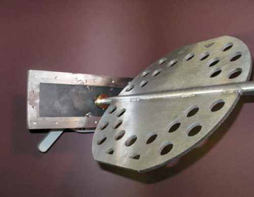
6. Coal flow-balancing valves from Combustion Technologies. Courtesy: Progress Energy
CO Analyzers. Two extractive CO analyzers supplied by Delta Instruments were installed adjacent to the permanent boiler O2 probes. The actual locations were selected following a traverse of the economizer outlet flue at various loads that identified the overall average CO and O2 reading locations.
Additional O2 Analyzers. Two Yokagowa O2 analyzers were added to the two existing Rosemount analyzers for the purpose of improving resolution and control of the overall O2.
Optimized Results
Now that the plant has a reliable and accurate primary airflow measurement along with real-time coal velocity data from each coal pipe, optimizing the mill primary air to feeder control operating curves was possible (Figure 7). Though the change illustrated in Figure 7 seems minimal, it did eliminate flame instability and layout caused by the previously unknown low combustion airflow.
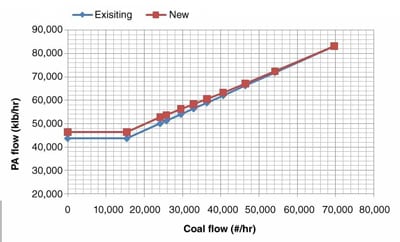
7. Asheville Unit 2 primary airflow versus coal flow. Source: Progress Energy
Previous CCM projects within Progress Energy were focused on mill with riffle distributors. Asheville Unit 2 has four pipes leaving each of the mills. As previously noted, coal adjustment valves were installed as close as possible to the mill discharge. Although it appeared to be a simple task of balancing the coal to each pipe, that was not really the case. Traditionally, operators would close off or otherwise restrict the pipe with the most coal flow. The result should be all the other pipes increasing or, better yet, the coal moving to the lowest pipe. It was at this point in the project that we learned a lesson and began to understand the subtleties of two-phase flow.
As we began adjusting the valves based on coal mass flow, we experienced how unpredictable the results were. It wasn’t until we factored in velocity that we were able to manipulate the valves to achieve an acceptable balance. The before and after velocity data illustrate the improvement in balancing mill discharge flows. (Download the pdf to see Figures 8 and 9. Figure 8 shows Asheville Unit 2 before final control adjustments; Figure 9 shows it after final control adjustments. Note in Figure 9 that the coal flow rates of each of the four mills are much closer in magnitude.
An unexpected result from the Asheville Unit 2 combustion modifications was increased NOx at comparable O2 levels from pretest conditions. These results were unexpected because with balanced fuel and air with automatic continuous air/fuel ratio control, it’s reasonable to expect the NOx to decrease. After more HVT traverses were taken, a theory was formulated.
Prior to the project, with air/fuel imbalances, localized NOx (due to severe reducing atmospheres) was so low that it reduced the overall NOx to approximately. 0.36 lb/Mbtu. However, these data were taken when several areas of the furnace had O2 readings very close to zero. Because the O2 profile was made uniform from the air/fuel balancing, the remedy was simply to safely lower the O2 setpoint. With a lower O2 setpoint, pre-project NOx values were achieved, but at the new conditions there was little to no CO and acceptable amounts of O2.
Final Test Results
As part of the project follow-up, post-CCM HVT testing was conducted. Testing was performed at the same location with boiler conditions being the same (except for balanced combustion) as during the prior test in August 2007 (Table 4). Table 5 contains the post-test data comparable to that summarized in Table 3.
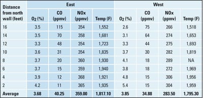
Table 4. Post-CCM project test data taken from Asheville Plant, Unit 2 on October 7, 2008. Source: Progress Energy
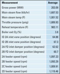
Table 5. Full load operating conditions of Asheville Unit 2 when post-CCM project test data found in Table 4 were collected. Source: Progress Energy
The primary project objectives of eliminating furnace reducing atmospheres and, thereby, tube deterioration, were not only met but exceeded. Secondary objectives that were achieved included decreased loss on ignition, efficiency improvement, and minimized boiler fouling. The furnace oxygen level through the combustion changes improved 300%. The improvements were a direct result of improving combustion by balancing coal flow and establishing uniform air/fuel ratios at each burner.
—Bill Kirkenir works at Progress Energy’s Asheville Plant. Dave Earley is with Combustion Technologies Corp./AMC Power.