One of the best indications of performance in the furnace is the quality of ash coming out of a power plant’s boiler. Ideally, all of the carbon is completely burned in the furnace before the products of combustion are quenched in the superheater. Perfect combustion remains the goal, but one that can never be achieved. However, we can come close.
Fly ash should be measured periodically (at least weekly) to determine its carbon content or loss on ignition (LOI). Low-NOx burners make it ever more difficult to reach low levels of carbon content in fly ash. However, when a furnace is performing well, the coal pulverizers are tuned for best fineness, and air/fuel ratios are optimum, then a realistic goal for carbon burnout is to reduce fly ash LOI to 3% to 5% or lower for eastern coals. With western Powder River Basin and lignite fuels, due to their high reactivity, fly ash LOI should be below 0.5%.
Obtaining representative samples of fly ash from very large flue gas ducts remains the largest challenge. For example, a typical 500-MW coal unit firing 8% ash content fuel will be passing about 40,000 pounds of fly ash per hour. The challenge is to obtain two representative 1-gram samples for LOI determination.
Why Doesn’t All of the Carbon Burn in the Furnace?
From our experience, there are three major factors that prevent complete burnout of carbon before it reaches the furnace exit:
- Insufficient furnace oxygen.
- Particle size that is too large (coal fineness is too coarse).
- Poor fuel and air distribution in the burner belt.
If there is insufficient well-distributed oxygen in the furnace to mix proportional amounts of fuel, it doesn’t matter what the furnace temperature is, the carbon will not burn. It’s important to remember the fundamentals such as ignition temperature, fuel, and oxygen that are required for combustion. Lack of oxygen in the furnace can be the root cause for one of three reasons:
- Insufficient total airflow.
- Fuel and air imbalance in the furnace (there may be an adequate oxygen level on an average basis, but some areas may have pockets of low oxygen levels).
- Falsely high oxygen indications from air in-leakage.
Side-to-side imbalances may be determined by taking fly ash samples from both the left and right sides of the boiler. One side of the furnace may show a carbon content of say 3%, but on the other side the LOI may be high, say 15%. This would indicate an imbalance that can lead back to the burners or secondary air. This type of information is valuable when tuning a boiler.
Larger fuel particle size contributes to high unburned carbon in two ways:
- More time is required for the complete combustion of the carbon char. Insufficient residence time, due to the furnace arrangement, is a big factor contributing to high LOI.
- Poor fuel fineness further contributes to high LOI from the resulting poor fuel distribution. Poor fuel distribution nearly always accompanies poor fineness.
Figure 1 illustrates how better coal fineness creates much greater surface area for optimizing the short residence time in the furnace. Finer pulverization also yields improved distribution through each coal pipe, as shown in Figure 2.
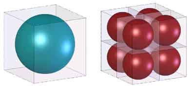
1. Fuel fineness is critical for maximizing boiler combustion efficiency. At half the diameter, the number of particles in a given volume increases by a factor of eight. In this example, the surface area of an equal weight of coal increases by a factor of four, and coal fuel distribution to the individual burners is improved. Source: Storm Technologies Inc.
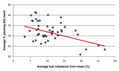
2. The relationship between fuel fineness and particle distribution in a typical combustion system is illustrated. Fuel fineness is measured by the percentage of fuel passing a 200 mesh screen. Source: Storm Technologies Inc.
In a fuel-sieving analysis, the constituents retained on the 50 mesh are of great concern because that is the portion of these particles with the least probability of complete burnout before reaching the furnace exit. Although 100% passing the 50 mesh is desired, this may be impractical, so a limit is usually placed at 99.8% to 99.9% passing 50 mesh. With well-tuned, carefully calibrated primary airflows and first-class coal pulverizer maintenance, a minimum of 75% passing 200 mesh and a maximum of 0.10% remaining on 50 mesh is a realistic goal.
How Is a Fly Ash Sample Obtained and Analyzed?
There are four approaches to measuring fly ash content and, therefore, the quality of fuel combustion in a boiler. Each is outlined below.
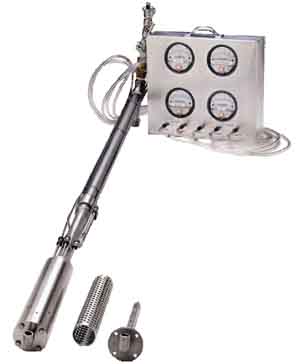
Fly Ash Sampling Method 1. For boiler testing, the most practical way to draw a representative fly ash sample for tuning is by traversing the boiler exit with a high-volume fly ash probe, as shown in Figure 3. The process requires a sample tip directed into the gas stream with a filter canister to collect the fly ash. An aspirator assembly is used on the end of the extension pipe to provide the suction. This usually requires one person and one hour to complete (depending on the duct size and fuel). It is simple in design: All that is needed is to turn the air on, insert the probe, and move it from point to point.

3. The high-volume “in-situ” fly ash sampler. Source: Storm Technologies Inc.
Remember that the intent of fly ash sampling is to obtain a representative ash sample from very large ducts. To do this requires that many points be sampled. For boiler acceptance testing, as many as one point sample every 9 square feet of duct area is usually collected by experienced test engineers. This is equivalent to one sample every 3 feet. Of course, this is impractical for weekly tests, but at least a reasonable number of sample points must be sampled. One sample every 25 square feet of duct area (one point every 5 feet) is typical.
Fly Ash Sampling Method 2. Using an isokinetic fly ash probe is the most accurate method, although this approach requires a minimum of two people, more time, and attention to detail during testing. A fecheimer probe is built into the head of the fly ash sampler, which measures the velocity in the duct. Once the velocity is measured, the sampling rate is matched with a manometer attached across an in-line orifice. The weight of the sample collected over a defined period of time can be used to calculate the ash flow rate in the duct. Other data taken during the test are the duct gas velocity, temperature, static pressure, and gas density. This level of precision is not needed for periodic performance testing.
Perhaps the biggest challenge is to obtain a representative sample. Our experience with the sampler shown in Figure 4 with a nozzle sized for “near isokinetic” sampling shows that it is quite sufficient for weekly sampling. However, we feel it is our obligation to state that the best and most accurate fly ash sampling method is the isokinetic sampler used for a representative number of sample points.
4. The isokinetic fly ash sampler. Source: Storm Technologies Inc.
Fly Ash Sampling Method 3. The multipoint fly ash sampler system in Figure 5 uses a probe that is essentially an arrangement of sample tubes installed in the flue gas duct to extract fly ash samples simultaneously from multiple points. By so doing, reasonably representative ash samples can be collected by one operator with minimal effort. Incorporated into this arrangement are thermocouples and flue gas sampling tubes so that representative temperatures and flue gas analyses can also be collected. This system was designed by Storm Technologies Inc., and a patent application has been filed.
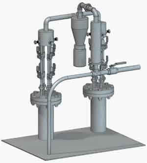
5. The integral “in-situ” fly ash sampler. Source: Storm Technologies Inc.
Fly Ash Sampling Method 4. The fourth and least accurate, but most common, method is taking “grab samples” from the ash hoppers. The three-part fly ash sample analysis method can determine whether the root cause of high fly ash LOI is due to the pulverizers or other combustion issues, such as poor airflow distribution, unbalanced fuel flows, or postcombustion duct air in-leakage. Because these ash samples can be very biased, they are not recommended for determination of furnace performance or combustion efficiency.
Fly ash samples are first burned to determine their carbon content either in a furnace or by the hot foil method. Both operate under the same principle: Heat the sample to about 200F to drive off the moisture, and then weigh the difference (WO). Then heat the sample to at least 1,600F and weigh the difference again (WF). The weight difference, (WO-WF)/WO will give the percent moisture and the percent unburned carbon, or LOI, in percentage of weight loss. When calculating the LOI it is assumed that all of the remaining combustibles are carbon.
If there is a problem with high LOI in the fly ash, a representative sample can be further analyzed to ascertain the root cause of the problem. The fly ash can be sieved through a 200 mesh screen, and the portion that passes the 200 mesh screen (fine particles) can be burned for LOI (Figure 6). If the fine particle LOI is higher than required, then the unburned carbon can be attributed to a combustion problem.

6. The three-part fly ash test separates coarse and fine particle samples (left) and a composite sample (right) that are weighed and compared to determine LOI. Source: Storm Technologies Inc.
If the fine particles are above 2% LOI for bituminous coal, this indicates that, although the particles are fine enough, there was not enough oxygen to complete combustion. If the LOI of the coarse particles is high, the problem can be traced back to the pulverizers. That’s because if the fine particle LOI is low, then the fine particles had enough oxygen and residence time in the furnace to burn. The unburned carbon in the larger particles indicates that the particles are too large to burn in the residence time allotted.
—Richard F. (Dick) Storm, PE is senior consultant for Storm Technologies Inc.