The operating environment within a condenser is extremely harsh, and in spite of the designer’s best intentions, sometimes tubes made of the best materials fail. The most important tube failure mechanisms typically result from different forms of corrosion and erosion. When it’s time to select new condenser tube material, you’ll need to consider the projected operating environment and failure mechanisms that material will be subjected to.
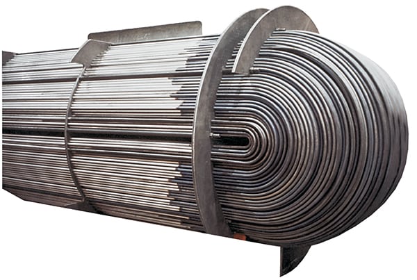
The steam surface condenser is the largest heat exchanger in a power plant, and the quality of the tubing within the condenser is critical for reliable plant operations. As discussed in “Optimizing Condenser Tube Selection,” earlier in this issue, a plant engineer has several materials from which to choose when specifying a replacement set of condenser tubes.
Those specifications must go well beyond mere material selection, however. The environment in which the tubes will operate, now and in the future, also must be described in the specifications. Upset and unusual operating conditions are often the cause of premature failure for tubing and piping materials in the power plant. Other failure modes are caused by changes in water chemistry due to leaks in other parts of the system, corrosion from unexpected sources, the impact of improper lay-up practices, and the effect of corrosion product transport to other parts of the system. This article discusses those failure mechanisms, what causes them, and how these types of failure can be avoided in the future.
Steam-Side Failure Mechanisms
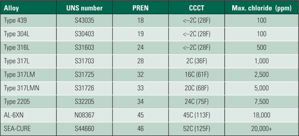
Because the total concentration of all contaminants in the steam cycle water chemistry is usually measured in parts per billion, steam cycle water chemistry is normally considered nonaggressive to most alloys. However, by actively condensing the steam, the condenser will concentrate gases that don’t condense at the same temperature as the steam. The most common contaminates include gases like oxygen, nitrogen, and ammonia (from decomposing oxygen scavengers). Stainless steels and titanium are resistant to these gases, but the copper-based alloys can be attacked by ammonia; admiralty brass and aluminum brass are the most susceptible. The ammonia can cause two types of failures: ammonia grooving and stress corrosion cracking (Figures 1 and 2).
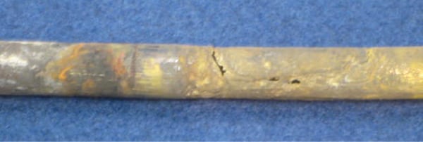 |
| 1. Ammonia grooving of aluminum brass. Courtesy: Plymouth Tube Co. |
 |
| 2. Intergranular stress corrosion cracking of admiralty brass. Courtesy: Plymouth Tube Co. |
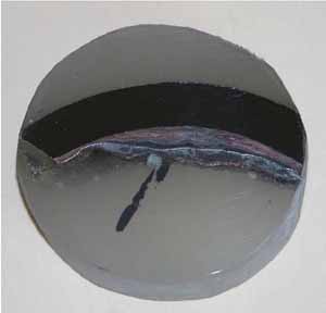
Dissolved copper, originating in the copper-nickel alloy condenser tubes, is also transported in the condensate throughout the system. The solubility of the copper decreases dramatically when the pressure significantly increases. Plating of surfaces often occurs in the boiler where it plates on the interior surfaces of tubes and on high-pressure turbine blades. Deposits on the boiler can depress the melting point of the boiler tube material, causing premature failure. This is called liquid metal embrittlement. When copper deposits in the turbine (Figure 3), it can cause as much as 5% decrease in power generation—worth millions of dollars each year.
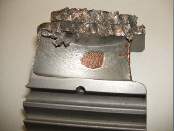 |
| 3. Copper deposits on the control stage of a high-pressure steam turbine. Courtesy: Pacificorp |
Cooling Water Attacks
In addition to general corrosion, many condenser tubes are susceptible to galvanic-driven mechanisms such as pitting and crevice corrosion. These failure mechanisms usually have two stages: an incubation or initiation period and a propagation mode. The time of initiation is rarely determinable. It could be as short as in a few weeks or may take years. Once initiated, the propagation mode can proceed rapidly, driven by the electropotential between the depassivated location and the surrounding area. Other tubes can be biologically attacked. The following sections describe each of these different forms of corrosive attack.
Pitting. Pitting corrosion is a highly localized attack that can result in through-wall penetration in very short order. Failures may occur in less than four weeks. Once a pit is initiated, the environment in the pit is more aggressive than the bulk solution because the material in the pit itself is stagnant. The pH in a pit can drop to below 2. When this occurs, the surface inside the pit activates. The potential difference between the pit and the more noble surrounding area is responsible for a galvanic attack. As the surface area of the anode (pit) is small and the cathode (the passive surface surrounding the pit) is large, current density can be quite high. For TP 316 in seawater, the voltage difference between the active site (a pit) and the passive region surrounding it can be 0.4 volts. These two factors will result in very high localized corrosion rates. Through-wall pitting in condenser tubes has occurred in less than three weeks.
The most common initiator of stainless steel pitting is the presence of chlorides in the condensate. Several alloying elements—such as chromium, molybdenum, and nitrogen—promote chloride resistance in this group of alloys. Not all of the alloying elements have the same effect. By investigating the impact of each element, a formula was developed that will determine the resistance of stainless steel to chloride pitting: PREn = % Cr + 3.3 (% Mo) + 16 %N.
PREn represents the “pitting resistance equivalent” number. This formula can be used as a quick reference on chloride resistance based upon just the chemistry of the alloy. In this formula, nitrogen is 16 times more effective and molybdenum is 3.3 times more effective than chromium for chloride pitting resistance. The higher the PREn, the more chloride resistance an alloy will have. It is interesting to note that nickel, a very common stainless steel alloying element, has little or no effect on chloride pitting resistance. However, it does have a profound impact on stress corrosion cracking.
Crevice Corrosion. Crevice corrosion is caused by the same galvanic driving force as pitting corrosion. However, because the crevice allows higher contaminant concentration than a pit (there is less opportunity to flush with freshwater), it is more insidious than pitting. The result is a lower-pH fluid in the crevice, resulting in attack at temperatures 30C to 50C lower than pitting in the same environment. Clean tubing may perform flawlessly for years but unexpectedly start to show problems once a deposit forms. The critical pitting temperature (CPT, above which pitting starts to occur) may be above the operating temperature, while the critical crevice temperature (CCT) could be below, initiating an attack.
The potential for crevice corrosion in chlorides is commonly measured by the ASTM G 48 Method B test. Researchers evaluated a large database of existing crevice corrosion data and compared it with the PREn number described earlier. The results were a series graphical relationships between PREn and the G48 CCT. Figure 4 is the result of that work with the additional modification on the right axis that allows it to be used as a tool for determining maximum chloride levels for an alloy of a particular chemistry, particularly at lower PREn.
Ferritic stainless steels were found to have the highest CCT for a particular PREn, above the duplex grade of the same PREn, followed by the austenitics. Each specific stainless structure provides a separate parallel linear correlation. After a typical or minimum chemistry is determined, the PREn can be calculated.
To compare the corrosion resistance of two or more alloys, a line is drawn vertically from the calculated PREn for each alloy to the appropriate sloped line for the structure. The vertical line should stop at the bottom line for austenitics, such as TP 304, TP 316, TP 317, 904L, S31254, and N08367. Duplex grades, such as S32304, S32003, S33205, and S32750, fall on the center line. The G48 crevice corrosion results of the ferritics, such as S44660 and S44735, follow the top sloped line. From this intersection, a horizontal line can be drawn to the left axis to determine an estimated CCT. A higher CCT indicates more corrosion resistance.
Maximum Chloride Levels. Although the level of chlorides in the condensate is the primary driver for pitting and crevice corrosion of stainless steel, other important factors have significant impact, include pH, temperature, presence and type of crevices, and potential for active biological species. On the right axis of Figure 4, the chlorine limit for a particular material is included to aid in the material selection decision. The scale is based upon having a neutral pH, 35C flowing water (to prevent deposits from building and forming crevices), which is common in many balance-of-plant and condensing applications.
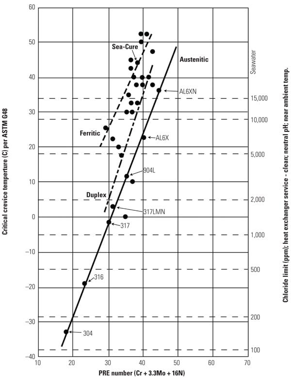 |
| 4. Critical crevice temperature and maximum chloride levels versus PREn of various stainless steels. Source: C.W. Kovach and J.D. Redmond, “Correlation Between the Critical Crevice Temperature ‘Pre-Number’ and Long-Term Crevice Corrosion Data for Stainless Steels,” presented at the NACE Annual Conference Corrosion 93, New Orleans, La. (April 1993). |
Once an alloy with a particular chemistry is selected, the PREn can be determined and then intersected with the appropriate sloped line. The suggested maximum chloride level can then be determined by drawing a horizontal line to the right axis. In general, if an alloy is being considered for brackish or seawater applications, it needs to have a CCT above 25C measured by the G48 test.
There are several important caveats you should be aware of when using this guide:
- If the temperature is higher than 35C, the maximum chloride level should be lowered.
- If the pH is lower than 7, the maximum chloride level should be lowered.
This guide assumes a clean surface. If deposits form, the pH can be significantly lower under the deposits, and the chloride levels may be much higher than the bulk water.
MIC. Microbiologically influenced corrosion (MIC) is often confused with pitting corrosion and typically occurs in water normally considered benign. The term “influenced” is used because the bacteria does not actively cause the corrosion. The bacteria forms a film or slime that creates a crevice. This isolates the water chemistry on the metal surface from the bulk water chemistry. The bacteria may also metabolate a product that can be very aggressive. Table 1 lists common bacteria types known to influence corrosion.
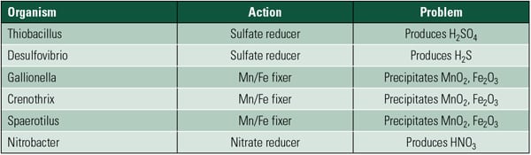 |
| Table 1. Bacteria commonly associated with MIC. Source: Plymouth Tube Co. |
The most common MIC attack in North America is a result of the influence of manganese-fixing bacteria (Figure 5). Although the mechanism is complicated, it’s also the most likely type of attack. The bacteria assists in oxidation of the soluble manganese to form an insoluble manganese oxide (MnO2) layer on the metal surface. This creates a crevice. When the operator detects an increase in condenser backpressure, sliming is suspected, and chlorination is initiated. The chlorination intended to kill the bacteria and assist in slime removal further oxidizes the MnO2 layer to a permanganate. Under that layer, the combination of the generated hydrogen and chloride ions reacts to form hydrochloric acid. The acid attacks the passive layer of the stainless steel, which initiates the attack.
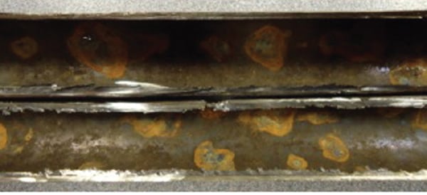 |
| 5. Manganese MIC-related pitting on TP 439 tubing after eight months of baseload service. Courtesy: Plymouth Tube Co. |
Studies have found that manganese concentrations as low as 20 ppb can initiate MIC. This mechanism most commonly occurs with TP 304 and TP 316, but higher molybdenum-containing grades and some duplexes have also been attacked. In general, an alloy needs a minimum CCT of 25C in the G48 crevice corrosion test to be considered resistant to MIC.
The Effect of Material Properties
The mechanical and physical properties for common copper base, titanium, and stainless steel tubing are available from a number of handbooks and online from tubing suppliers. These properties—such as ultimate strength, yield strength, and hardness—are important to consider when selecting a new condenser tube.
One important concern is the tube’s erosion resistance. Erosion resistance is a function of the ability of the protective layer to remain attached to the substrate and the strength (hardness) of the substrate directly below the protective layer. Two types of erosion commonly cause problems in the power industry: flow-accelerated erosion-corrosion and water droplet/steam impingement erosion.
Flow-Accelerated Erosion-Corrosion. When the fluid velocity is so high that it will actually “scrub” the protective film from the metal surface, then flow-accelerated erosion-corrosion is possible. Conversely, higher velocities are desirable because they increase the heat transfer rate and keep the tube surfaces clean, reducing the surface resistance to flow. In general, a velocity of 6 feet per second (fps) is considered the minimum for keeping the tube surface clean. Biofilms have been known to develop at lower flow rates. Table 2 summarizes the maximum safe fluid flow velocities inside of condenser tubes of different materials.
 |
| Table 2. Commonly accepted maximum water flow rates for erosion-corrosion. Source: Plymouth Tube Co. |
Older traditional condenser designs restricted flow rates to the 6 to 7 fps range to protect the copper alloy–based tubing. With the elimination of copper in modern condensers, modern flow rates are in the 9 to 10 fps range. If your existing condenser has marginal thermal performance and can handle a higher cooling water flow rate (velocity), then significant performance improvements can be made, assuming pump modifications to increase flow rate are possible. At the higher flow rates, stainless steels and titanium are immune to erosion and corrosion. In many systems, the payback on investment may be less than one year. Additionally, the higher flow rates will result in cleaner tubes.
Water Droplet/Steam Impingement Erosion. Under certain unique conditions, it is possible to experience erosion of the tube outside surface caused by the localized impact of high-velocity water droplets (Figure 6). This can occur near diverter plates that may focus the high-speed wet steam onto the tube or during other upset conditions. It often occurs in steam dump areas when the outlets are not properly designed.
 |
| 6. Steam water droplet erosion of stainless steel tubing in a nuclear power plant. Courtesy: Plymouth Tube Co. |
The resistance of the tubes to this form of erosion is a direct function of the hardness of the metal substrate below the protective oxide. In general, higher hardness provides higher erosion resistance. Using a water droplet impingement device developed by Avesta Sheffield, alloys can be ranked by time to failure. The process is to graphically plot material hardness versus time to failure, so a relationship can be determined. Other material grades can then be added by comparing the hardness. Using titanium grade 2 as the reference, with a value of 1, the relative resistance of other grades can be ranked, as presented in Table 3.
 |
| Table 3. Relative erosion resistance based on water droplet impingement tests. Source: Jüri O. Tavast, “Steam Side Droplet Erosion in Titanium Tubed Condensers—Experiences and Remedies,” ACOM 3-96, April 1996. |
Hydrogen Embrittlement
Titanium and superferritic stainless steels, such as S44660 and S44735, can embrittle with exposure to monotonic hydrogen. This commonly occurs in water systems that have poorly controlled cathodic protection. The problem is prevented when the system is controlled so that the voltage is maintained at a potential more positive than –750 millivolt. When the voltage is more negative, hydrogen bubbles develop on the surface. During the development stage, monotomic hydrogen develops, which easily diffuses into the material.
Embrittlement of titanium occurs as an intermetallic phase develops on the surface in contact with hydrogen. This layer grows with exposure and eventually progresses through the entire wall. These embrittled tubes have little mechanical strength. Tubes can be broken simply by leaning on them. This process is not reversible.
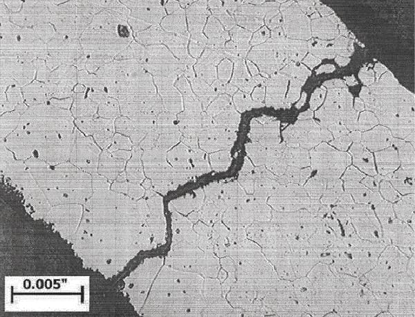 |
| 7. Intergranular hydrogen embrittlement cracking of S44735 superferritic stainless steel. Courtesy: Plymouth Tube Co. |
Fortunately, unlike titanium, the hydrogen in superferritic stainless steels resides in interstitial sites in the lattice structure and does not form a compound. This allows the embrittlement in the stainless to be easily reversed. Once the source of the hydrogen is eliminated, the atoms in the stainless diffuse out of the structure, and the ductility returns. This normally occurs within 24 to 48 hours at 80F, and the ductility can return as quickly as within one hour at 200F. One caution is that multiple hydrogen charging and discharging may create microcracking that can then propagate (Figure 7).
— Daniel S. Janikowski (djanikowski@plymouth.com) is technical manager of Plymouth Tube Co.