Many automation engineers are coming face to face with real fieldbus applications for the first time. Fieldbus (the use of digital communications networks for distributed instrumentation and control) is a wonderful technology with many benefits, but fieldbus installation requires some additional considerations over and above normal 4-20 mA projects. In this article, I present some of those issues and show you how to deal with them.
Don’t get hung up on which fieldbus to choose. “Fieldbus” is a generic term for a variety of communications protocols using various media, but all are simply a means to an end. What you want at the end of the project is a satisfactory and functional control system, and practically every installation will use multiple fieldbuses to accomplish the many tasks required. For example, you may use Foundation Fieldbus (www.fieldbus.org) in the process plant, DeviceNet for a power-line carrier network, and ProfiDrive (process field bus) to run motor drives. Every distributed control system (DCS) can easily integrate all these functional plant buses into the Ethernet-based control room bus.
In process control engineering, “fieldbus” normally means Foundation Fieldbus (FF) or ProfibusPA (PA); both fieldbuses are perfectly adequate and widely used around the world in refineries and process plants as enhancements to 4-20 mA two-wire devices. This article focuses on FF and PA physical layer implementation.
Fieldbus Power Supplies
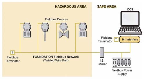
A fieldbus segment (Figure 1) begins at an interface device at the control system. On an FF H1 system the interface is called an H1 card; on a PA system, it is a Profibus DP/PA segment coupler. In terms of signal wiring and power requirements for the segment, FF and PA are identical:
• Minimum device operating voltage of 9V.
• Maximum bus voltage of 32V.
• Maximum cable length of 1,900 m (shielded twisted pair).
• Communications at 31.25 kHz, Manchester encoded.
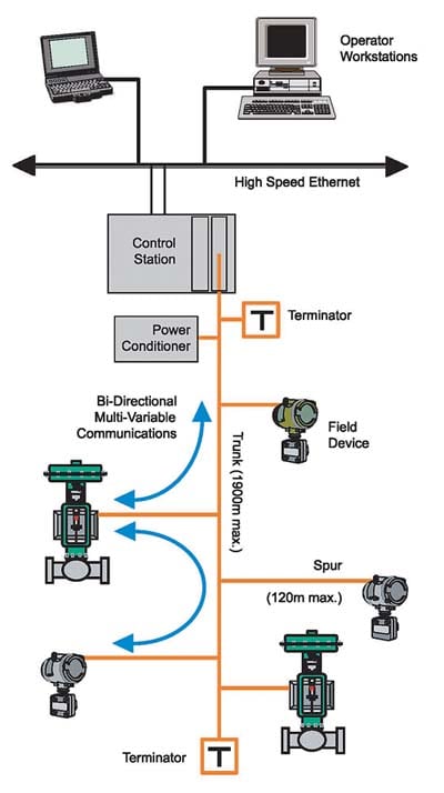
1. Standard fieldbus segment. Courtesy: MooreHawke
The DC power required by devices on the bus is normally sourced through a fieldbus power supply or “power conditioner” (Figure 2), which prevents the high-frequency communications signal from being shorted out by the DC voltage regulators. Typical power conditioners make 350 to 500 mA available on the bus and usually incorporate isolation to prevent segment-to-segment crosstalk.
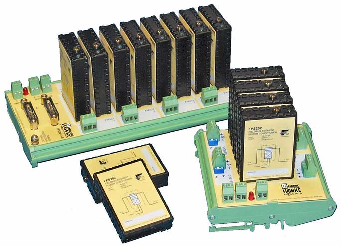
2. A fieldbus power conditioner prevents the high-frequency communications signal from being shorted out by the DC voltage regulators. Typical power conditioners make 350 to 500 mA available on the bus. Courtesy: MooreHawke
In FF segments, the power conditioners are separate from the H1 interface card and are often installed in redundant pairs to improve overall reliability. For PA systems, the DP/PA segment coupler usually incorporates the power conditioning component. There is no absolute requirement for the DC source to be independent for each segment, but most designs provide segment isolation via DC/DC converters.
Note that fieldbus power conditioners are not the same as COTS (commercial off-the-shelf) power supplies, which, if directly connected to any segment, will immediately damp out all communications. FF/PA systems carry both DC power and digital communications on the same wire pair, and a standard 24V DC power pack would effectively short-circuit the communications signal. The power supply therefore requires low-pass “conditioning” to filter out that signal, and this conditioning may be “active” (through the use of notch filters, for example) or “passive” (via series inductance).
Of course, fieldbus power supplies can fail while in service, so it is usually a good idea to specify power supplies that are redundant (one unit can continue delivering power when the other one fails), that can be “hot-swapped” (a new one can be replaced without shutting down the segment), and that have some sort of alarm that notifies maintenance or operations when a problem occurs. Another good feature is built-in surge protection to protect the DCS system from lightning impulses from the field.
Redundant supplies can be constructed as needed for FF segments, but PA segments are constrained by the standard DP/PA segment coupler design, which incorporates field power conditioning within the DP/PA protocol converter and only allows redundant power conditioning in the fault-tolerant version.
Segment Calculations
When calculating how many devices can fit on a fieldbus segment, the primary factors to be taken into account are the maximum current requirement of each device and the resistance of the segment cable (because of voltage drops along the length). The calculation is a simple Ohm’s law problem, with the aim of showing that at least 9V can be delivered at the farthest end of the segment, after taking into account all voltage drops from the total segment current.
For example, driving 16 x 20 mA devices requires 320 mA, so if the segment is based on cable with 50 ohms/km/loop and a 25V power conditioner, the maximum cable length is 1,000 m to guarantee 9V at the end. Then:
• Voltage available for cable = 25 – 9 = 16V
• Allowable resistance = 16V / 0.320 A = 50 ohms; equivalent to 1,000 m cable
Note that many users also specify a safety margin on top of the 9V minimum operating voltage to allow for unexpected current loads and for adding additional devices in the future. Some users also allow a safety margin in case one or more fieldbus devices fail from a short circuit. I’ll discuss that below.
The calculations must be done for each segment. An engineer must add up all the power requirements of all the fieldbus transmitters, valve controllers, and other devices on the segment, and then factor in the length and resistance of all the cables to make sure that 9V can reach the farthest devices. Fieldbus devices can require anything from 10 mA to 25 mA, so 20 mA is a reasonable estimate for mental calculations.
In most cases, the fieldbus device manufacturer will supply the necessary data, but be wary: Sometimes they are mistaken. In one case, a customer found that valve controllers specified to draw 10 mA actually required 25 mA when configured in a particular way. When plant staff powered up the segment, they found that discrepancy the hard way and had to add an entire segment to accommodate the high-powered controllers.
Terminators
In PA and FF, the communications signal is current modulated at 31.25 kHz, 20 mA p/p. Terminators are required at each end of the segment cable (the square “T” boxes in Figure 1) to prevent line reflections (which may otherwise result from open-ended cables) and to source/sink the communications current.
The terminator circuit is very simple: 100Ω resistor and 1µF capacitor in series across the segment. The end-of-line resistor provides a nominal load for the communications signal, and the capacitor stops the DC supply from draining through the resistor. Two terminators at 100Ω give a nominal 50Ω load for the communications current (20 mA p-p) and a signal voltage for receiving devices of 1V p-p.
If instruments worked during lab or staging tests but not in the field, in many cases it’s an installation problem. Simply put, the technicians didn’t set the segment terminators properly. Instruments can behave erratically, drop off the segment mysteriously, and generally raise havoc—all because the terminations are not set properly.
Two terminators are required per segment, one at each end. With one terminator, the signal will be higher, and with three or four terminators, the signal will be lower. Many field devices won’t accept signals at 2V p/p and may unexpectedly reset. With three or four terminators, the signal can be so low that it is unusable. The absolute minimum signal that devices must be able to recognize is 150 mV p/p.
Some users may test a segment in a lab or at the vendor’s site. In such a case, under carefully controlled conditions, the segment may actually work with incorrect terminators. However, segments rarely work in the field when not terminated properly.
Careful installation management to ensure the correct number of terminators is essential. It is unfortunate that many installation subcontractors pay little heed to the terminators and either forget them completely or enable them all if they are part of the device couplers, neither of which allows the segment to operate properly. Often, physical inspection of junction boxes and field enclosures is the only way to locate and correct the terminator position, which is a significant delay to the commissioning process.
Most device couplers (Figure 3) use manual on/off DIP switches to terminate couplers. In a segment, the last device coupler should contain the terminator (Figure 4), and all couplers between the last coupler and the H1 card should have their terminator switches set to off. Diagnosing the problem often requires physically examining each device coupler to determine if the switches are set properly throughout the segment.
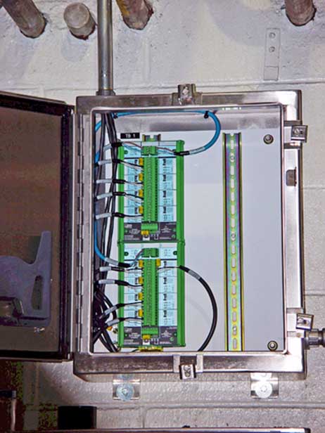
3. A device coupler provides short circuit protection on each spur. Some device couplers have automatic segment termination. Courtesy: MooreHawke
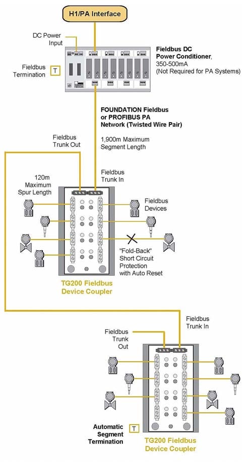
4. Terminators (square T boxes) must be turned on at the beginning and the end of each segment. Courtesy: MooreHawke
Automatic segment termination simplifies commissioning and start-up. It automatically activates when the device coupler determines that it is the last fieldbus device coupler in the segment; if it is, it terminates the segment correctly. If it is not the last device, it does not terminate the segment, since the downstream device coupler will assume that responsibility. No action—such as setting DIP switches—is necessary by the installation person to terminate a segment properly.
If a device coupler is disconnected from the segment accidentally or for maintenance, the automatic segment termination detects the change and terminates the segment at the proper device coupler. This allows the remaining devices on the segment to continue operation.
Fieldbus Cable
One of the central themes of using fieldbus for process control is that it should be as practical as possible. Power and signal should be available on the same cable, and that cable should not be fundamentally different from conventional instrument cable already in common use.
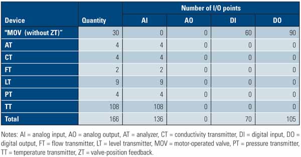
Some cable manufacturers take advantage of the uninitiated by offering “fieldbus” cable in the same way as they make “intrinsically safe cable” (which is the same as ordinary instrumentation cable but with an alternate color sheath and significantly extra cost). In general, if a cable is already in use for instrumentation and control, it is almost certainly fine for FF/PA use. Typically, 0.8mm2 cable is used, with shield on individual spurs and with overall shield if used as part of a multi-core cable. The table lists the typical cables used in fieldbus applications.
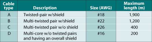
Maximum length of cables. Source: MooreHawke
Conventional instrumentation cable may not have digital communications parameters included on its datasheet (effective impedance at 31.25 kHz, attenuation rate in dB/km, etc.) and so its performance in fieldbus applications cannot be guaranteed. The Fieldbus Foundation is about to release a test specification for cable that will allow manufacturers to test conformance to a proper performance specification.
Tip: If you intend to use cable glands to seal the cable entry into a device coupler or junction box, check that the fieldbus cable used is properly “round”; many cheaper two-wire cables have a distinct “lay” evident in the outer sheath of the cable, which will inhibit successful sealing.
Fieldbus Wiring
Fieldbus cable may be virtually indistinguishable from 4-20 mA cable, but field wiring techniques and accessories are definitely different. Fieldbus systems are simple to design because all the device wire pairs are connected in parallel but, in practice, any attempt to fill a box full of terminals and just “jump” between all positives and all negatives will result in a rats’ nest of cables within the enclosure. This may be acceptable in some plants, but it will lead to all sorts of maintenance problems once the installers have left the site.
A better idea is to use device couplers—junction boxes specifically designed for fieldbus implementation. These units automatically provide the necessary system interconnections without confusion and greatly speed up the process of device installation. They should incorporate the required terminator with either manual or automatic activation.
Short Circuits
Short circuits are a common problem in any fieldbus installation. Maintenance technicians can jostle cables, corrosion can weaken connections, and vibration from pumps and motors can loosen cables and connectors. Segment designers must be concerned about what might happen to an entire fieldbus segment if any single instrument shorts out.
It is highly recommended that the segment designer incorporate some form of spur short-circuit protection, which may be active or passive in design. Passive protection is very simple and usually is provided by fuses on each spur that “blow” to disconnect any individual fault. This approach is inexpensive and very reliable, but it does require manual intervention: Someone has to replace the blown fuse (after repairing the fault!).
Device couplers often provide active spur protection in two basic forms: “current-limiting” and “fold-back.” Both types auto-reset after fault removal and both normally incorporate LEDs to indicate spur status.
The current-limiting technique limits the amount of power the short circuit can draw to between 40 mA and 60 mA (the amount is vendor-dependent), but it also holds that fault on the segment continuously. Although this design protects the segment from the initial short, the additional current draw from the short can deprive other instruments on the segment of power, overload the segment power supply, and possibly cause catastrophic failures on the segment. If current-limiting designs are to be used, ensure that your segment’s power supply can cope with these additional loads.
For example, a segment may have 10 measuring devices plus two valves connected via 1,000 m of 50-ohm nominal cable (say, 250 mA total). In this case, the trunk voltage drop equals 12.5V, which allows 12.5V at the farthest device. However, if a short occurs at a spur and an additional 60-mA load is “locked in” to the segment, this takes away enough power so that devices receive less than 9V (8.5V for the farthest device), and some will drop off the segment. If two shorts occur, all the devices could drop off, and an entire process unit might go down. Therefore, if current-limiting protection is used in a device coupler, you must provide a 60-mA safety margin. That is, do not install as many instruments as the segment can theoretically power; instead, leave at least three spurs empty.
An alternative design is the fold-back variety, where any faulty spur is switched off and that load is completely removed from the segment. The fold-back technique disconnects the shorted spur from the segment, thus preventing loss of an entire segment. The fold-back technique has a logic circuit on each spur (Figure 5) that detects a short in an instrument or spur, disconnects that spur from the segment, and illuminates a red LED that can be seen by maintenance personnel.
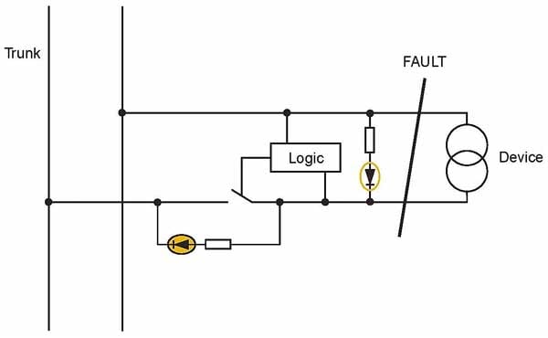
5. A “fold-back” circuit, available with some device couplers, removes a short circuit from the system. This differs from “current-limiting” short-circuit protection, which limits the short to 60 mA but keeps it on the segment. Source: MooreHawke
With fold-back device couplers, you don’t have to worry about spur failures and can have confidence about placing more devices on fieldbus segments. Because the cost of H1 cards ($2,500) and other segment hardware can be cost-prohibitive, being able to place more devices on a segment can save considerable money. A typical FF segment, consisting of an H1 card, power supply, device couplers, and cables, can cost about $5,000. A large process plant may have hundreds if not thousands of devices. If the “safety margin” approach is used, where the entire capability of fieldbus is not used, the cost of all the extra fieldbus segments can become substantial.
For example, assuming that a typical fieldbus segment with modern fold-back protection can accommodate 16 x 20 mA fieldbus devices, it requires 63 fieldbus segments to support 1,000 devices, at an approximate cost of $312,500. If a safety margin approach must be used because of current-limiting protection, and each segment can now only accommodate 10 instruments, then 100 segments are needed, at an approximate cost of $500,000. Simply by specifying fold-back short-circuit protection, an end user can save $188,000.
Redundant Operations
Fieldbus systems offer many advantages to process companies, not the least of which is the elimination of “home run” wiring and the snake’s nest of twisted-pair wiring in field-mounted marshalling cabinets. Fieldbus eliminates all this because it allows up to 32 devices to be wired together over a single twisted-pair digital “network” or segment.
However, fieldbus systems present a problem: What happens if the segment cable or the power conditioner driving the segment cable fails? Depending on where the failure occurs, the entire segment—with all 32 devices—could go down. An entire process unit could then go off-line.
One answer is to provide redundancy wherever possible, to ensure that any single failure cannot take down an entire process unit. Redundancy can be employed in two basic ways:
• With redundant power conditioners.
• With redundant trunks.
A redundant power conditioner (Figure 6) has two power conditioners, both powered by a load-sharing pair of 24Vdc power supplies. Such a system can survive the failure of either 24Vdc power supply or either power conditioner. If a failure occurs, the unit automatically and smoothly switches all loads to the backup unit. It also has an alarm output to indicate that a failure has occurred. If any of the individual modules fails, replacements can be hot-swapped into place without shutting down the segment. The power conditioner modules plug into a DIN carrier (Figure 2), which can accommodate four or eight modules, to provide redundant power for two or four fieldbus segments. For a redundant configuration, each pair of power conditioner modules requires two power supply inputs and one connection to the fieldbus segment. Installation is not difficult, because a redundant power conditioner requires no changes to be made to the fieldbus segment, device couplers, or interface card.
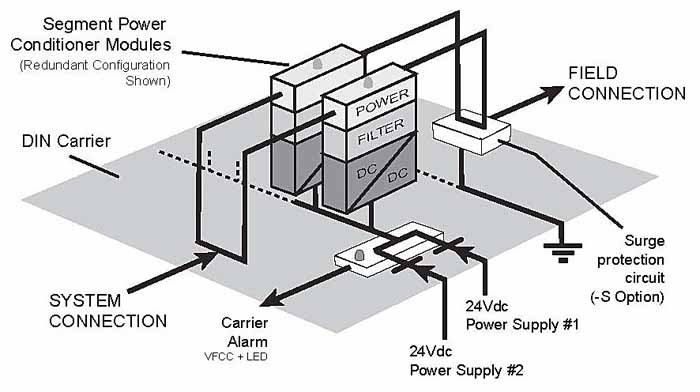
6. A redundant power conditioner, such as this TRUNKGUARD unit from MooreHawke, provides redundant power conditioners and has two sources of supply. If any single part fails, it will continue to power the segment. Courtesy: MooreHawke
However, in most cases, the DIN carrier can accommodate simplex (nonredundant) or duplex (redundant) power conditioners, but not both. That is, you cannot mix redundant and nonredundant power conditioners in the same DIN carrier. Therefore, when determining which critical fieldbus segments will have redundant power conditioners, take care to plan fieldbus wiring so that the critical segments are routed to the proper DIN carrier.
Redundant Trunks
In a critical process segment, it may be necessary to provide redundancy on the main segment cable or “trunk.” Doing so protects a process unit from going down if something happens to the main cable, such as a forklift running over the cable, water getting into the conduit, or any of a host of problems that can occur in the field. If the system can be switched to a backup or redundant segment, then the process can continue operating.
It is important to note that fieldbus instruments can continue to operate by themselves if communication to the host DCS is lost. In FF installations, the field devices can talk to each other and continue monitoring and control operations according to the last setpoints provided by the DCS. However, they cannot continue to operate if the trunk cable is broken, because the cable provides power to the instruments.
One way to provide redundancy is to duplicate the entire segment (Figure 7). This requires a duplicate interface card (such as an H1 card for FF), a duplicate power conditioner, duplicate cable, duplicate device coupler, and duplicate field instruments. When one segment fails, the DCS switches over to the backup segment.
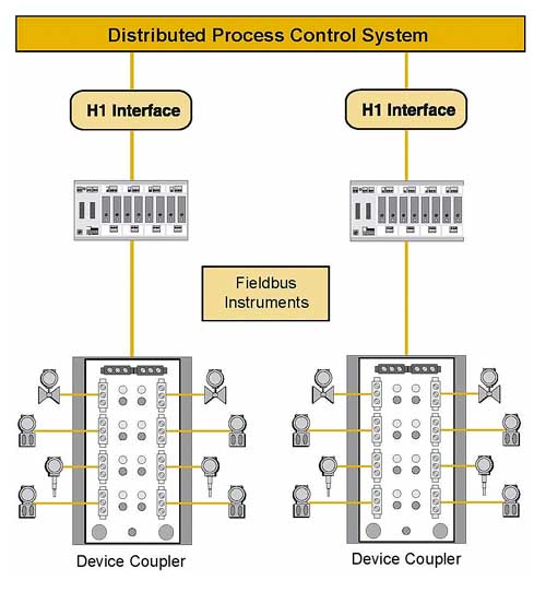
7. One type of redundant fieldbus segment requires duplication of every component, from H1 cards to field instruments. If one segment fails, the DCS switches to the second segment. Courtesy: MooreHawke
Though this is an extremely expensive hardware solution, it does provide redundancy for every device in the segment. No matter what fails, a backup exists. To install such a system, you must determine the conditions that will cause the DCS to switch segments, and program the DCS accordingly. Check with your DCS vendor to make sure the DCS can identify a segment failure. Some can only determine that an interface card has failed.
If the latter is the case, you must devise some way of determining that a segment failed. It is possible to set up a software scheme that periodically polls the fieldbus devices, asking for device status. If none of the devices responds, the software could conclude that the segment has failed, and call for the DCS to switch to the backup segment. However, maintenance procedures then become very complex, with special overrides to cater for out-of-service devices, and so on.
An alternative method is to use a fault-tolerant segment with parallel interface cards, parallel power conditioners, dual trunks, and one field device coupler (Figure 8). This eliminates the need to duplicate field instruments and avoids difficult maintenance issues while improving the segment MTTF by seven to 10 times at virtually no cost. The power conditioners determine when a cable break occurs, cut power to the failed trunk, and use the backup cable immediately. This “fault-tolerant” approach simplifies installation because it does not require any special programming of the DCS.
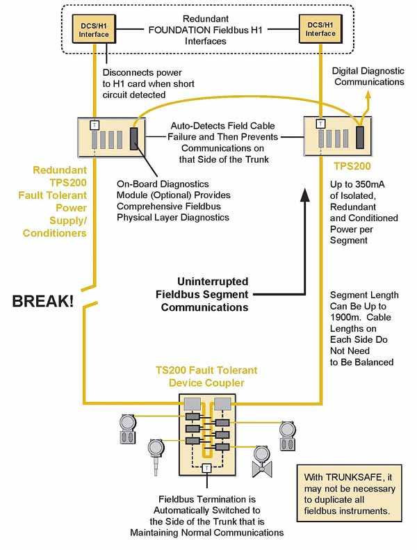
8. A fault-tolerant fieldbus system has two segments. If a fault occurs in one leg of the system, it automatically uses the other leg. It is not necessary to duplicate the field instruments. Courtesy: MooreHawke
When the fault-tolerant system detects a cable break, it deprives the H1 card of power, so the DCS knows that a failure occurred and can switch to the backup H1 card. It also gets an alarm from the power supply, indicating that a failure occurred. And, because the power conditioners have auto-termination capability, the proper segment termination is set automatically.
The fault-tolerant system does not require any other special hardware; in fact, the DIN-rail power conditioner modules can be installed in the same DIN rack as conventional modules. No special installation wiring is necessary in the field. It is probably advisable to route the two segment cables differently, so that the same physical incident—such as a wayward forklift—does not take out both cables at the same time.
If a certain type of field instrument is prone to failure, a redundant instrument can be installed and wired into any spare spur on the device coupler. The DCS, of course, has to be configured accordingly, so it recognizes a device failure and knows to switch to the backup instrument.
Working in Hazardous Areas
Three methods are available for installing fieldbus in hazardous areas:
• Intrinsically safe systems.
• Explosion-proof cabinets.
• Nonincendive equipment.
Intrinsically safe (IS) circuit designs limit the electrical energy at the device to a level below the explosive limits of the environment and remain safe with a component failure. An intrinsically safe circuit, as defined by the National Electrical Code (NEC), is “a circuit in which any spark or any thermal effect is incapable of causing ignition of a mixture of flammable or combustible material in air under prescribed test conditions.”
An IS circuit uses a safety device such as a safety barrier to limit the power in the hazardous environment and, because it is considered to be very safe, this type of system can be worked on while it is energized without gas clearance testing (commonly referred to as a “hot work permit”).
An explosion-proof design and installation (flameproof/Exd in Europe) requires that if a fuel were ignited inside the device enclosure, the enclosure would contain the energy of ignition and disperse it into the classified area at a level low enough to prevent a secondary ignition from occurring outside the enclosure. Explosion-proof designs require special installation methods, as well as requiring the electrical devices and enclosures to be rated explosion-proof (NEMA 7/9) for the proper area classification. This type of system cannot be worked on while energized without a gas clearance certificate.
A nonincendive circuit, as defined by the NEC, is “a circuit, other than field wiring, in which any arc or thermal effect produced under intended operating conditions of the equipment is not capable, under specified test conditions, of igniting the flammable gas-air, vapor-air or dust-air mixture.”
Nonincendive circuit designs do not take component failure into consideration. Consequently, they offer a reduced level of safety compared with the IS circuit design and are therefore only allowable in Division 2/Zone 2. There are two fundamental types: non-arcing, which cannot be worked on while energized without gas clearance testing, and energy-limited, which is more like a poor man’s IS that can be disconnected “live.”
Though all three methods have been used for fieldbus installations, the most popular—especially in Europe—is intrinsic safety. One might consider this a historical hangover: IS systems were great for analog electronic modules that needed frequent access in the field and for the adjustment of limit switches on valves.
Fieldbus devices require no physical adjustments in the field or otherwise, and all changes are made through the segment communications, so putting yourself through the pain of IS fieldbus (and it can be very painful indeed) is not necessary at all!
However, company specifications don’t always follow technology very fast, so here’s how to minimize that heartache.
Installing Intrinsically Safe Systems
Intrinsically safe methods for fieldbus include:
• Entity
• FISCO
• Split architecture Entity
An “Entity” system requires “barriers”—that is, devices that limit the amount of current that can enter the hazardous area (Figure 9). In general, IS fieldbus was originally based on the Foundation fieldbus FF816 specification. Entity systems are highly reliable, especially when based on simple resistive current-limiting, which allowed Entity parameters for field devices to be at least 24V/250 mA/1.2 W. These barriers allow about 80 mA for Gas Groups A, B, C, D (NEC)/II (IEC), or four devices per segment.
9. Entity systems require a “barrier” that limits power to the segment, and thus limits the number of fieldbus devices. Courtesy: MooreHawke
The major problem in installing an Entity system is the large number of barriers required and the amount of cabinet space required in the “safe area” (Figure 10). Because each barrier can work with only four fieldbus devices, a large number of fieldbus segments are required. For example, a conventional (nonhazardous) segment with 16 x 20 mA fieldbus devices would have to be separated into four segments in a hazardous area. Each segment requires an H1 or PA interface card, power supply/conditioner, barrier, trunk cable, and a device coupler.
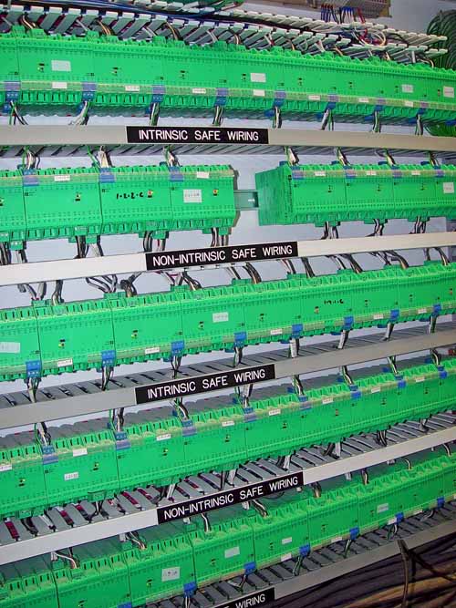
10. Typical Entity wiring system. Courtesy: MooreHawke
FISCO (Fieldbus Intrinsically Safe Concept) provides 115 mA, instead of just 80 mA, allowing a FISCO power supply to power about five conventional 20-mA fieldbus devices.
Note that FISCO fieldbus instruments are designed to take lower current (12 mA or 15 mA), and some manufacturers use that value to claim that FISCO systems drive more devices; however, be aware that less current usually means less capability in the devices themselves.
FISCO also has a drawback: The complexity of the FISCO electronic current-limiting design itself and the requirement to have multiple such circuits in series (current-limiting must still be available even if a circuit fails in an unsafe way) means that the overall mean time to failure (MTTF) of these units is much lower than users might expect. FISCO systems are also much more expensive because of the high cost of the FISCO power supplies and fieldbus devices.
Installation of FISCO is similar to that of an Entity system: The FISCO power supplies are mounted in the safe area. The rules for using FISCO allow only 1,000 m of cable in total and only 60-m spurs—about half that of a “normal” fieldbus. This should not pose a problem in most installations because of the limited number of devices on each segment.
A split-architecture system (Figure 11) puts part of the barrier in an isolator and part of it in each of the spurs of a field-mounted device coupler. By splitting the intrinsically safe current-limiting method in this way, the system can put a full 350 mA on the trunk that leads into hazardous areas with Gas Groups C and D and still have intrinsically safe spurs that match FF816 Group A and B approved devices. This overcomes both the FISCO and conventional Entity restrictions on available current. Up to 16 devices can be put on a segment—nearly four times as many as an Entity or FISCO system.
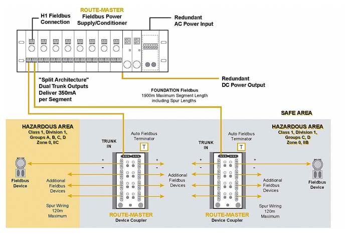
11. A split-architecture system allows a full 350 mA on the segment and does not limit the number of fieldbus devices that can be supported. Courtesy: MooreHawke
Installation is much simpler, because fewer devices and segments are required. In general, a split-architecture system requires only 25% of the cabinet space of an Entity or FISCO system.
One problem you may encounter during installation is incompatibility of conventional and FISCO devices. In previous implementations, the split-architecture design has been based on device Entity parameters of 24V, 250 mA, and 1.2 W (values that the IS power supply must guarantee not to exceed and which are specified in IEC61158-2 and associated documents). FISCO devices, on the other hand, are associated with Entity values of 17.5V, 380 mA and 3.8 W, so it has not been possible for Entity systems to easily demonstrate compatibility and safety with FISCO devices. This had become an issue with some device manufacturers that have specified FISCO approvals for their devices but not Entity approvals, and with some older devices that have Entity but not FISCO approvals.
A recent enhancement in split-architecture systems is the incorporation of FISCO compatibility at the field device coupler. Having FISCO and Entity compatibility at the device coupler in a split-architecture design enables all users to implement intrinsically safe fieldbus with any desired mix of approved devices without the limitations in cable lengths and reduction in MTBF (mean time between failures) that results from a pure FISCO system.
Removing and Replacing Instruments
Maintenance people want to be able to remove devices from fieldbus segments in hazardous areas without turning off the whole segment and without going through complex disconnection procedures and mechanical interlocks, if they can be avoided.
In Zone 1 applications, simply specify a device coupler approved for Zone 1 that also has a magnetic interlock on each spur. The technician puts the key in the slot, which isolates the spur and makes it accessible for rewiring without shutting down the segment. This works particularly well if IEC/AEx standards are being followed, since that particular device coupler can fit inside a low-cost GRP enclosure (Exe/AExe approved) with spurs fully accessible in Zone 1. Some device couplers are designed and approved for use in Zone 1 and Zone 2 with flameproof Exd devices.
For flameproof Division 1 applications, live de-mateable plug/socket combinations are available from many manufacturers. If an application demands live exposure in Division 1 or connection into Zone 0, then field barriers can be used that allow intrinsically safe spurs to be attached to the nonintrinsically safe trunk.
Cost is determined by the amount of time a maintenance technician must spend removing and replacing instruments. If the process is laborious, it might take hours to follow all the safety procedures. If the process simply requires a key, then an instrument can be disconnected in a few seconds.
Simplify Your Installation
Many of the installation headaches discussed in this article can be minimized through careful selection of fieldbus equipment at the beginning of a project.
Few end users realize that fieldbus components, such as power supplies and device couplers, are not manufactured by the DCS vendor. Instead, they are provided by associated suppliers, such as MooreHawke, Relcom, and Pepperl+Fuchs. Therefore, even if a user is buying an Emerson DeltaV or a Yokogawa Centrum or a DCS from any other supplier, it is possible to specify fieldbus components separately. Note that the choice of physical layer product makes no difference to the DCS operation. All fieldbus power conditioners and device couplers simply enable the fieldbus power and communications to work; they do not communicate with the DCS.
To simplify installation of your fieldbus system, evaluate the components carefully from the various suppliers. Look for:
• Automatic segment termination on device couplers to eliminate termination problems during installation, start-up, and regular maintenance.
• Fold-back short-circuit protection (which disconnects a shorted device from the spur) to eliminate the need to leave spurs empty.
• Power supplies with built-in power conditioning, redundancy, and surge protection.
Fieldbus is an exciting technology that offers many benefits to end users—especially early adopters. Implementation of real fieldbus systems is still a new experience for many engineering companies, and many subcontractors are wiring up devices without any real understanding of the different requirements and problems presented by fieldbus systems. Keep some of the guidelines describe here in mind when ordering your fieldbus system and when dealing with your installation subcontractor to help ensure a successful installation.
—Mike O’Neill (moneill@miinet.com) is director of international sales for MooreHawke, a Division of Moore Industries.