Most preventive and predictive maintenance practices for steam turbines focus on keeping lube oil pure, vibration levels under control, and all inlet and non-return valves ready to stroke at a moment’s notice. Internal leaks of steam cannot be identified easily or measured directly, but they can be detected by performance engineers with calibrated eyeballs and instruments.
Southern Company’s team of plant maintenance, central office technical/maintenance, and performance testing/steam path audit personnel has an excellent track record for spotting steam path problems. By closely monitoring turbine performance trends, the team can catch, diagnose, and resolve many problems early—often during the next unit outage.
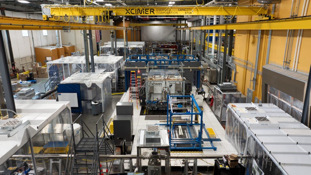
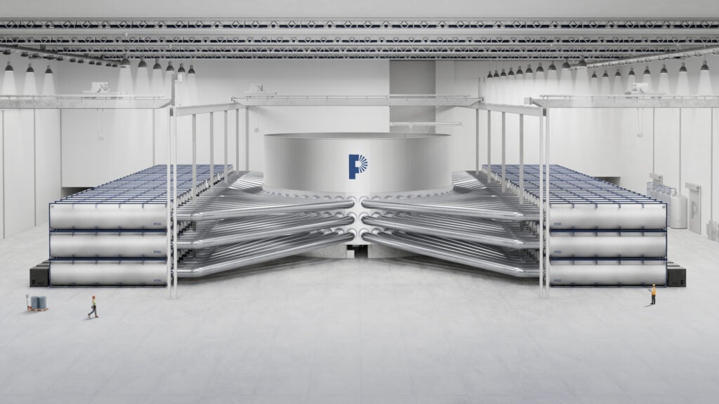
How are internal leaks identified, and which parts of a steam turbine are most prone to leakage? This two-part series answers those questions, beginning with an overview of the symptoms and causes of the most serious and unmanageable leaks—of excessive steam from a turbine’s high-pressure (HP) to intermediate-pressure (IP) section. Part I concludes with three case studies of GE turbines (Figure 1) that illustrate how the concepts apply in practice to these specific machines. In next month’s POWER, we’ll scrutinize Westinghouse (Figure 2) and Allis-Chalmers turbines.
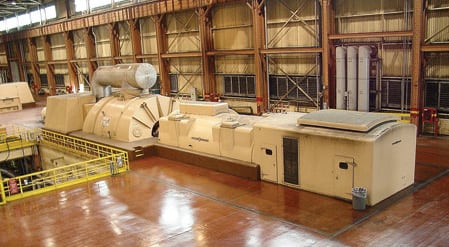
1. Smooth operator. Southern Company’s Plant Branch Unit 2 is a 320-MW GE steam turbine. The unit began commercial operation in 1967. Courtesy: Southern Company Generation

2. Making power. Unit 4 at Southern Company’s Plant Branch is a 500-MW Westinghouse steam turbine that began operation in 1969. Courtesy: Southern Company Generation
Say aah
The symptoms experienced by a turbine suspected of internal leakage must be inferred from tests and indirect observations. Medical doctors diagnose patients that way every day. But whereas humans can verbalize their complaints, steam turbines can only speak in the language of lost performance and efficiency. It’s a lot easier to detect blood bypassing a cardiac valve than to diagnose HP to IP seal leakage.
The diagnosis begins with the understanding that increased HP to IP leakage can have several causes. Seals damaged or weakened by misalignment, poor start-ups, or multiple temperature excursions will increase leakage, for example. For utility-grade turbines, age is definitely a factor, especially with HP inner shell distortion or loose/overstretched bolting causing leakage at the horizontal joint. A water induction incident will cause seal rubs and HP inner shell distortion.
The typical time between turbine overhauls has increased from four years in the past to as much as eight to10 years today. Lack of thoroughness and poor quality of turbine inspections also may be an issue. In particular, it’s important to insist that the inspection include the main steam inlet expansion rings in the turbine’s lower inner shell.
Losing load
A turbine’s output and reliability can be affected by high internal leakage. An enlarging internal leak will initially increase the unit’s capacity in a manner similar to reheat spray. The cycle flow restriction in the first few stages of the HP turbine will be bypassed. Eventually, the effects of reduced boiler reheater flow will cause overheating of the reheater tubes and more tube leaks. Load may have to be curtailed to avoid overheating the reheater.
Other problems could occur, too. On the mechanical side, loose nuts on the HP inner shell could "liberate" their washers. If they enter the IP turbine inlet, they could cause severe damage to buckets. In some turbine designs, the washers could just as easily enter the LP turbine.
Nuts and bolts aside, the thrust balance of the HP-IP turbine also can be affected by a change in internal flow distribution. It may not be possible to achieve full load following such a change if it triggers a thrust bearing alarm.
Other clues that you may have an excessive internal leakage problem include those that follow.
Trouble controlling reheat temperature. If fuel and boiler conditions haven’t changed but reheat spray flow has been increasing with time, this could be a sign that internal leakage has increased and is bypassing the reheater. The situation could evolve into one where the flow capacity of the reheat spray is "topped out." At this point, the only alternatives for control would be to reduce load or to lower superheat temperature.
Apparent (measured) IP efficiency changes. Very high (>94%) values of measured IP efficiency (from the hot reheat to the LP crossover) are good signs for all GE units. But for Westinghouse turbines, the same values are indicative of high leakage to the IP turbine inlet, and extremely low values are symptomatic of high leakage to the LP crossover (bypassing most of, or the entire, IP turbine).
Turbine pressure changes at valves wide open. Decreasing first-stage pressure, coupled with increasing downstream pressures, could indicate flow bypassing the HP turbine. (The effects of reheat spray should be accounted for on the downstream pressures.) The main steam flow calculated from the first-stage pressure curve will decrease, whereas the main steam flow determined by the feedwater flow (plus superheat spray flow, if applicable) will increase. Some older units with main steam and hot reheat flow nozzles will show a trend of decreasing hot reheat flow (after accounting for reheat spray differences, and assuming the performance of the cold reheat HP feedwater heater has not changed).
Turbine thrust bearing changes. Although the phenomenon has been rarely reported at Southern Company Generation (SCG) plants, at several other plants the position of a steam turbine thrust bearing has been changed by abnormal flow distribution in the HP and IP sections of opposed-flow turbines (there was less steam flow in the HP turbine than in the IP turbine).
Turbine shell temperature differences. Verified differences of over 100 degrees F between the upper and lower shell metal and steam temperatures could be a sign that an internal leak is cooling an upper or lower section.
Quick reaction required
Excessive leakage entering the IP turbine reheat bowl can be (but is not always) marked by a noticeable increase in measured IP efficiency across the load range. Likewise, excessive leakage entering the LP crossover pipe will normally lower measured IP efficiency.
Determining the amount of internal leakage requires conducting a relatively inexpensive HP-IP enthalpy drop test with test-quality instruments. The main steam and hot reheat temperatures are varied to observe the change in measured IP efficiency. This is called the Booth-Kautzmann test (see box, p. 33, #1). SCG calls it the "temperature split test." A large (>1%) change in efficiency from one test to the next is a sure sign of high internal leakage. Ideally, these routine tests should be conducted at least once per year with either calibrated plant or test-quality instruments. Tests conducted with other kinds of instruments can produce inconclusive results. Remember to account for miscellaneous items, such as water legs, when making measurements of static pressure.
As part of its testing procedures, SCG tries to maintain at least a 30- to 40-degree F spread between temperatures, at stable conditions. It is very important to have at least three testing conditions—normal superheat/reheat, normal superheat/lower reheat, and low superheat/higher reheat—at the same load. For boilers that have trouble generating reheat steam that is hotter than main steam, another option is to use various amounts of reheat spray to achieve two conditions: low reheat and lower reheat.
The level of difficulty in achieving the temperature variance depends on the boiler’s design and fuel as well as the patience of the unit operator and test engineer. Variables and equipment that the operator can control include superheat spray, reheat spray, boiler O2, burner tilts, gas recirculation fan operation, selective sootblowing, top-firing pulverizers, and convection zone gas bypass dampers. Some units achieve the variance at full load, others only at lower load.
It’s a good idea (for sanity’s sake) to maintain the difference between the assumed level of leakage enthalpy and that of main steam enthalpy constant for each test calculation. For GE units, SCG usually assumes that the leakage is the average of the test main steam and cold reheat enthalpies. If main steam inlet snout rings are suspected of contributing to excessive internal leakage, it’s reasonable to assume that its enthalpy is identical to main steam inlet enthalpy.
For Westinghouse and Allis-Chalmers units, which have more variations in arrangement, the leakage enthalpy should be more carefully selected. Using the average of the main steam and cold reheat enthalpies has proved sufficient for calculating the leakage enthalpy’s effect on the LP crossover. For later Westinghouse units, which have bell seals that can leak to the crossover, SCG assumes the leakage is that of main steam if a bell seal is suspected to be the major culprit.
SCG engineers use a Microsoft Excel spreadsheet with a Steam Tables add-in to calculate and plot test results. Our simple method does not require any measured flows—only test pressures and temperatures. The three derived lines should intersect at approximately the same point (Figure 3). From our experience, it is relatively easy to achieve good intersection with a high leakage rate, due to the influence of the leakage enthalpy and flow. For a low leakage rate, the lines do not intersect as well, because the leakage has less effect on the apparent IP efficiency. If a high leakage rate is indicated, you should first look for clues, such as those you might find in a review of the last turbine outage report work and any recent operational excursions.

Issues specific to GE turbines
For a General Electric combined HP-IP steam turbine, the design (heat balance) leakage from the HP to IP turbine, through the N2 packing, is typically 2% of hot reheat flow. When the turbine is new, this is usually the only significant HP to IP leakage. But as it ages, components other than N2 packing can become contributors, including:
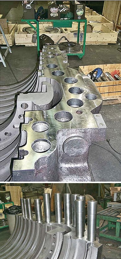
- Upper and lower main steam inlet snout rings. A clearance of 0 to 2 mils is standard for conventional rings, and gaps over 10 mils can produce large amounts of leakage (Figure 4).
- The N2 packing head’s horizontal joint, and how it fits into the inner shell (if separate) (Figure 5).
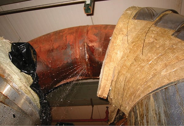
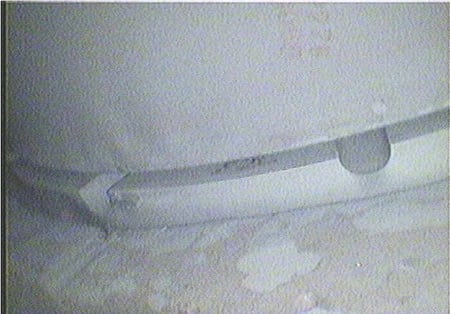
- The HP inner shell horizontal joint (if the shell distorts or the joint develops a loose bolt) (Figure 6).
- The turbine blowdown pipe’s snout/piston rings (the pipe is horizontal on smaller units and vertical on larger ones)
- The first-stage pressure-flanged probe, and how it fits in the lower inner cylinder.
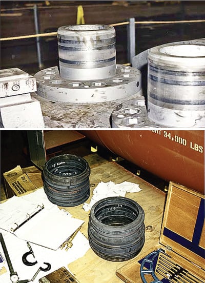
4. First contact. Some main steam inlet snout rings for a 250-MW General Electric steam turbine. Note in the top photo the good contact between the inner ring and the snout pipes. The bottom photo shows the inner and outer snout ring stacks after removal. Courtesy: Southern Company Generation
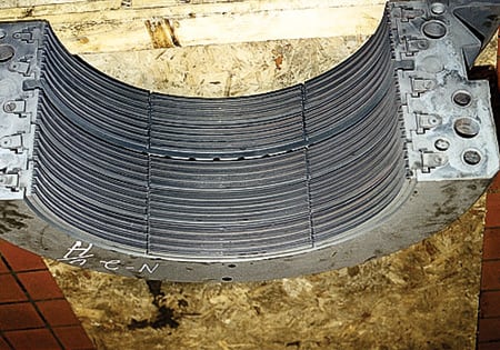
5. Packing heat. A typical N2 packing seal, packing head, and horizontal joint for a 250-MW GE steam turbine. Courtesy: Southern Company Generation

6. Nuts to that. Loose stud nuts caused this leakage around the HP inner shell horizontal joint of a 125-MW GE steam turbine. Courtesy: Southern Company Generation
Any or all of these leakages, along with those through the N2 packing, flow to the IP turbine inlet (or reheat bowl). Increased leakage will cause a rise in the measured (or apparent) IP efficiency (from the hot reheat to the LP crossover). The increase is not due to a gain in blading efficiency but, rather, to lower-enthalpy HP turbine steam mixing with higher-enthalpy hot reheat steam. The heat rate penalty is caused by the leakage of steam around the HP turbine and boiler reheater.
Ruling out abnormalities
The Booth-Kautzmann test defines two methods for determining HP to IP leakage. The first method, for measuring total leakage requires the temperature split test. This method will determine the total HP to IP leakage and is the more important test to conduct. SCG abandoned the temperature split test in the early 1990s on GE turbines because we assumed any other abnormal HP to IP leakages were taken care of in turbine overhauls; we were wrong. We resumed this testing in 1996 after we could not resolve some performance issues; this proved to be a blessing, as we found many problems with excessive HP to IP leakage resulting from HP inner shell joint and snout ring leakages.
The second method, which determines only leakage through the N2 packing and any through the blowdown pipe snout rings, involves opening the turbine blowdown valve and measuring the change in apparent IP efficiency that results from diverting the N2 packing steam to the condenser. (Some GE units do not have this valve, and on others it is not large enough to pass all the N2 packing flow.)
If there are no other leakages to the IP turbine, this method will provide a true measure of the IP blade path efficiency. The value can be converted to units of leakage using Figure 3 in Booth’s paper (see box). As shown by numerous comparisons of the blowdown test to steam path audit clearance measurements, it is quite accurate at calculating N2 packing leakage.
If there is no significant difference between total leakage and N2 packing leakage, then there are no other abnormal internal leakages. A significant difference between the two numbers indicates the existence of an abnormal leak, most likely either in the HP inner shell horizontal joint or in the main steam snout rings.
Where and how to inspect
A visual inspection of the ring contact area on the HP inner shell pipe only indicates the condition of the inner main steam inlet snout rings. The condition of the alternating outer rings can only be assessed by unstacking the rings and carefully measuring the clearances. The outer rings may carry telltale signs of steam erosion of the shell, but the signs remain invisible unless the rings are unstacked.
GE turbines larger than 300 MW have three sets of snout rings. Leakage through the outer shell and inner shell rings of each set goes to the IP reheat bowl, where it contributes to overall HP to IP leakage and affects the apparent efficiency of the IP turbine. Because leakage through the nozzle box set rings bypasses the first stage, it would affect only the HP turbine. Although this leakage has a minor effect on efficiency, it could have a major impact on flow capacity.
For GE steam turbines built in the mid-1960s and later, there is a mid-span balance port flanged connection that can be used to inspect for loose HP inner shell nuts. The balance port may not be shown on the turbine cross-section diagram if it is not exactly top dead center. In any case, the turbine instruction book will contain a page describing the balance port access.
Use a borescope to check for loose nuts (Figure 7). One turbine vendor offers a high-temperature borescope service, so the procedure can be performed during short outages while the turbine is still hot. Using the balance port also allows inspection of the IP inlet stationary blading, which typically erodes after many years of service. Another inspection approach that may work on older units is to remove an intercept valve and use a long borescope.
7. Scope of work. This loose nut atop an HP inner shell washer was found with a borescope inserted into the mid-span balancing port of a 250-MW General Electric steam turbine. Courtesy: Southern Company Generation
If excessive leakage is detected, reducing it will require taking these steps:
- Replacing the N2 packing seals if they have excessive clearance or broken teeth. Proper alignment and a controlled start-up after the turbine outage are critical to maintaining the seal clearances.
- Replacing snout rings (for main steam and the N2 packing blowdown pipe) that have excessive clearance, taper, or erosion. The snout pipes themselves may be worn or eroded enough to require refurbishment (Figure 8).
- Weld build-up and machining the HP inner shell horizontal joint surface, including an evaluation of its studs and shell threads (Figure 9). Leakage can actually flow up through shell holes, eroding the studs. The stud nuts should be "sounded" with a hammer to determine if any are loose prior to disassembling the unit. One possible retrofit, which SCG has used very successfully on one unit, is to switch to a through-bolt stud arrangement. Whatever the arrangement, it is very important to know both the stud material and the nut tightening specs.

8. Triple play. The main steam inlet snout pipes of a 320-MW GE steam turbine with three sets of snout rings. Courtesy: Southern Company Generation
9. Fixing the fix. Weld build-up on the HP inner shell joint of a 75-MW GE steam turbine required machining and the replacement of studs. Courtesy: Southern Company Generation
Outage inspections to correct an internal leakage problem may create the need for some unexpected IP turbine repair. On two occasions, a stud nut washer came loose from the HP inner shell nut, broke into pieces, and was propelled into the IP turbine, damaging its buckets and covers (Figures 10 and 11).

10. Nice catch. This broken stud nut washer from the HP inner shell of a 350-MW GE steam turbine was found lodged in the stationary blading of the IP section. Courtesy: Southern Company Generation

11. Nut on the loose. Here are the IP turbine buckets damaged by broken pieces of the stud nut washer. Courtesy: Southern Company Generation
After an outage to fix excessive HP to IP leakage, the turbine should be thoroughly tested to ensure that the work was successful. In SCG’s experience with GE turbines, total internal leakage can be reduced to less than 3% of hot reheat flow leakage.
The remainder of this article presents three case studies of successful evaluation and repair of GE turbines suffering excessive internal leakage. Remember to consult the August 2007 issue of POWER for similar stories concerning Westinghouse and Allis-Chalmers turbines.
Case study #1: Excessive HP to IP leakage in a 250-MW turbine
At this plant, a high level of turbine internal leakage was having an "invisible" impact on unit heat rate. The rise in heat rate, in 1999, would not have been diagnosed if the leakage test had not been conducted, because the turbine was running smoothly, with normal levels of noise and vibration.
At the time, 10 years had passed since the turbine had had its total HP to IP leakage measured using the temperature split test. The test had indicated that both total leakage and N2 packing leakage were both relatively low: 3.5% of hot reheat flow.
However, in 1996, a routine HP-IP test pointed to some type of damage (pressure changes) in the initial stages of the IP turbine. Just prior to the unit’s scheduled 1997 major outage for turbine maintenance, an open reheat spray block valve caused a turbine water induction event that affected the turbine’s HP exhaust stages and inner shell. The outage inspection found the HP inner shell horizontal joint open near the HP inlet and detected several loose inner shell stud bolts.
SCG engineers didn’t believe that the bolts had been loosened by the water induction. Rather, they concluded this had occurred prior to the 1996 test, as a loose washer had disintegrated, entered the IP turbine, and caused damage the prior year. The HP inner shell required stress relief to correct distortion and some older cracks that had been weld-repaired. All new studs were installed on the inner shell. As the last outage in 1995 had indicated possible leakage, alternative main steam inlet snout rings were installed as part of the outage work.
Post-outage 1997 temperature split testing measured total HP to IP leakage at 7.5% of hot reheat flow, while blowdown testing indicated that N2 packing leakage was only 1%. The big differential pointed to a significant HP to IP leak. Because the snout rings had been replaced, they became prime suspects. As part of the investigation, discussions were initiated with the snout ring supplier.
In 1998 both tests were repeated. This time, measured total HP to IP leakage was 8.8% of hot reheat flow, and N2 packing leakage was 2.1%. Significantly, both percentages were increases.
In 1999 the tests were repeated a third time. Now, total HP to IP leakage was 16.6% of the hot reheat flow (nearly twice the previous level), while N2 packing leakage remained constant at 2.0%. By this time, the unit’s rolling-average heat rate had increased significantly, so an outage for inspecting the turbine was scheduled for early 2000.
The 2000 inspection revealed loose nuts on the HP inner cylinder, some with three to four turns open. The original nuts had been replaced by pinned nuts and washers that had been incorrectly installed. A measurement of the open joint area read 40 mils. The pinned nuts and washers then were installed properly. Although the inner snout rings appeared to be fine, there were signs of incipient problems with outer rings that led to a decision to replace all rings with conventional rings.
The post-outage HP-IP test to confirm the "fix" was delayed due to budget constraints. So the unit’s heat rate continued to rise throughout 2001, and plant personnel attributed the gains to "a boiler problem."
The post-outage test was finally conducted in January 2001. Discouragingly, it found total HP to IP leakage practically unchanged, at 17%, and N2 packing leakage at 3.5%.
In February 2001, SCG engineers arrived at the plant to perform a borescope inspection of the nuts of the turbine’s HP inner shell, using the midspan balance flange hole. Once again, there was evidence of loose nuts and—possibly—stretched studs.
GE was consulted for an alternative "fix." The company proposed installing Inconel through-bolts to replace the stud arrangement, and that was what was done prior to the major scheduled unit outage of 2002. For a few months preceding the outage, the leakage problem got bad enough to force a unit derate, because of excessive overfiring.
Inspection during the 2002 outage confirmed that nuts were loose on both sides of the HP inner shell and that the threads had been damaged by overstretching the studs (Figure 12). The through-bolt arrangement was installed.
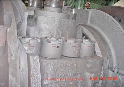
12. Let’s tighten up. Loose nuts in the HP inner shell can increase internal steam bypass leakage. Shown is a 250-MW GE steam turbine. Courtesy: Southern Company Generation
The post-outage HP-IP test was conducted in June 2002. Total HP to IP leakage had significantly decreased to 4.5%, with N2 packing leakage at 2.0%. Although the numbers were not back at design, they were a tremendous improvement. The improvement was also reflected in the unit’s rolling-average heat rate (Figure 13). Although the correction of some boiler economizer performance problems during the prior outage also lowered the heat rate a bit, there was no doubt that decreasing HP to IP leakage was a much bigger contributor. To this day, the heat rate of the unit remains under 10,000 Btu/kWh.
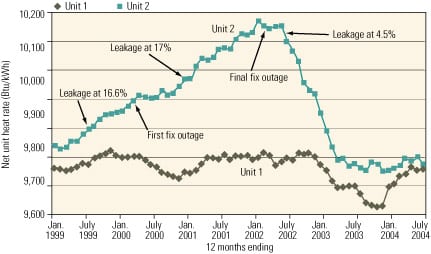
13. Rolling average net unit heat rate. Unit heat rate improved significantly after the successful 2002 repair outage. Courtesy: Southern Company Generation
Case study #2: Excessive HP to IP leakage in a 250-MW cross-compound turbine
A 250-MW cross-compound turbine also was experiencing higher-than-normal heat rates in 1997, due to an unknown HP to IP leakage. As in the first case study, eight years had passed since the last temperature split and blowdown tests, which found the levels of total HP to IP internal leakage and N2 packing leakage fairly close, at 1.8% and 1.5%, respectively.
In 1995, as part of a major unit overhaul, the turbine’s main steam inlet snout rings were replaced with those of an alternative design. The subsequent performance test did not include a temperature split test; a blowdown test measured N2 packing leakage as "low."
A temperature split test was finally conducted on the unit in 1997; it measured total HP to IP leakage at 4.5%, with N2 packing still low at 1.5%. The disparity pointed to an undetected HP to IP leak.
In 1998, prior to the unit’s major annual overhaul, another temperature split test measured total leakage at 5.7% and N2 packing leakage at 2.7%—both increases. During the 1999 outage, when technicians unstacked the snout rings, they bore signs of leakage along the outer ring to shell bore fits as well as leakage across the ring stack flat surfaces. The main problem, engineers decided, was that the outer seal rings had expanded too much into the shell bore, mushrooming the softer shell material and causing "blue-blush" to exfoliate and migrate to the ring-to-ring flat surfaces. Additionally, the snout ring material did not match the snout bore material on two of the four snouts. This caused those inner rings to not seal due to identical thermal expansion coefficients. The main steam inlet snout rings were replaced with conventional rings. The HP inner shell joint closure was found to be tight. The worn N2 packing was replaced.
Following the repairs, the two diagnostic tests were performed in 1999. They measured total leakage at 2.8% and N2 packing leakage at 2.0%—both decreases. The closeness of the two values indicated the presence of very little other leakage. Three more performance tests conducted in 2000, 2001, and 2005 verified that both leakage types remain low. However, both tests were again conducted earlier this year, and they measured total leakage at 7.0%, with a large contribution coming from the N2 packing leakage (3.7%). During this year’s scheduled outage of the unit, SCG expects to replace the N2 packing and check the condition of the snout rings and HP inner shell joint.
Case study #3: Excessive HP to IP leakage in a 500-MW supercritical turbine
Post-outage tests of a 500-MW supercritical turbine in 2003 measured total HP to IP leakage at 4.2%, with a 1% contribution from N2 packing. Routine testing in late 2005 indicated that total leakage had increased to 8.5%. At that time, N2 packing leakage could not be measured because the turbine blowdown valve would not open.
The unit’s outage records revealed that the bolting of the turbine’s HP inner shell had been replaced, but there were some misunderstandings because the bolt material was also changed, which could affect stretch requirements. The decision was made to open up the HP-IP turbine, with the expectation of finding loose HP inner shell bolting.
Unexpectedly, however, the source of the leakage problem was found to be broken N2 packing teeth (Figure 14). The HP inner shell joint was found to be tight. There was also one broken stud on the N2 packing head. It was determined that the N2 packing teeth broke because of looseness in the tooth slot; the packing had been re-toothed twice.

14. Needs dental work. These broken N2 packing teeth were found on a 500-MW GE supercritical steam turbine. Courtesy: Southern Company Generation
After replacing the N2 packing, the unit was retested in early 2006. Total HP to IP leakage was found to be 4.2%, with a 2% contribution from N2 packing leakage (as measured by a turbine blowdown test). If the turbine blowdown valve had worked properly in 2005, it would have been clear then that all of the prior increase in total leakage was due to leakage through the N2 packing.
The author wishes to recognize the outstanding turbine maintenance performed by James Carlson and Bill Broos of Southern Company Generation’s Mechanical Field Services department. The enlightening test results and discussions in this article are due to their efforts and the hard work of SCG’s Generating Plant Performance department.
—Warren Hopson, PE, is a Southern Company Generation principal engineer for Generating Plant Performance. He can be reached at whhopson@southernco.com.