The operation of solar thermal power plants differs substantially from that of fossil-fired plants, as the sun determines the generation rather than market demand. However, design of the power island to minimize water usage is very similar to that of a fossil plant. This renewable technology requires renewed thinking of its water systems’ design.
Solar thermal plants exhibit many unique design features that provide both advantages and challenges to water systems designers. One advantage is that the plant operating profile is generally more consistent and predictable than that of a fossil-fueled plant. On the other hand, obtaining water is a challenge for any power plant, particularly for concentrating solar power (CSP) plants that are usually sited in arid regions. Special conveyance and treatment systems may also be required if the water quality is poor in those regions, increasing both capital cost and system complexity.
Wastewater treatment presents an additional challenge for the plant designer. Most CSP designs include evaporation ponds. Although minimizing pond size minimizes capital cost, doing so also tends to increase treatment system complexity. Complete or partial zero liquid discharge (ZLD) systems may be required. (See “Fundamentals of Zero Liquid Discharge System Design” in the October 2011 issue of POWER or the archives at https://www.powermag.com.)
Air-cooled designs present special challenges as well, primarily with wastewater treatment. There’s no large cooling tower available to accept oil/water separator effluent, boiler blowdown quench water, or other waste streams that are typically recycled in the cooling tower. While of relatively good quality, these waste streams present reclamation challenges and again add complexity to the treatment system design. Auxiliary cooling towers may be available, but they may not be large enough to accept the full volume of these waste streams.
There are no easy fixes or rules-of-thumb that apply to the design of a CSP water system. This article presents a water treatment system design approach for CSP plants that minimizes complexity and cost while still providing reliable and sustainable plant performance.
Predicting Water Usage
The amount of water used in a CSP plant, much as in a conventional power plant, is based on the number of operating hours. Calculating solar thermal plant operating hours is relatively straightforward. Several computer programs are available that will compute an estimated plant dispatch profile based on the incident solar energy at a specific geographic location. Table 1 illustrates typical solar energy collected at a site and an estimate of the electricity generation potential from a CSP plant.
The operating profile lists plant operating hours for a typical day for each month of the year. In January, for example, the operating profile indicates that the plant begins producing power at approximately 8:30 a.m. and ceases power production at approximately 3:30 p.m., a total of 7 hours. The plant produces 765 MWh during the operating period, assuming the power output is averaged over each 1-hour period. Ambient temperature during the operating period averages 73F.
Thermal design data allows accurate calculation of the plant general water demands (cooling tower evaporation, boiler blowdown, and other uses) but rarely provides sufficient granularity to accurately model water usage for the typical solar plant operating profile. Rather, a thermal design case usually provides expected plant output and general water demands for a given set of ambient conditions and a specific plant configuration, assuming steady-state operation.
The typical thermal design process would take the following design approach. Table 2 lists the thermal design cases studied for this 255-MW design output project, a design point that reflects the gross maximum system generation at any time of the year. So the “typical winter” design case for this example would take the design output of 255 MW each hour at an ambient temperature of 50F and a wet bulb temperature of 41.7F.
There are two problems with this approach to determining this thermal design case. First, it’s the wrong temperature for January operation: The average ambient temperature during January operating hours (not the daily average) is 73F. Second, it assumes a continuous plant power output of 255 MW during each hour of operation.
The temperature issue can be resolved simply by running additional thermal design cases. The traditional design cases (hot day, annual average, winter, and so on) are important, but they should be supplemented with additional thermal design cases that model the average ambient conditions for a typical day for each month of the year during plant operating hours, not 24-hour temperature averages. Although this may seem excessive, this data granularity is critical for accurately predicting plant water usage. Using the average annual case or some mixture of the traditional thermal design cases increases the uncertainty in water usage calculations.
The power production calculation can also be easily resolved. Remember that the thermal design case in this example lists steady-state plant power production at 255 MW based on the maximum possible generation at any time of the year (Table 1) and the design data at that design point (Table 2). However, the plant never actually reaches this level of power production in January. The amount of energy from the sun is relatively low, and the sun doesn’t shine long enough.
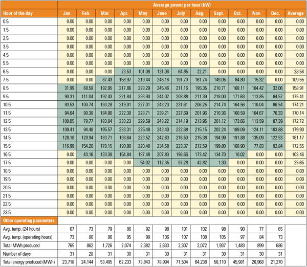 |
| Table 1. A typical CSP plant operating profile. The yellow regions indicate no solar energy is recovered. The green areas are the hours during which solar energy is recovered. The average power in kilowatts is shown for each hour. Because the time period is 1 hour, the power in kilowatts is numerically the same as the energy generation, in kilowatt-hours. Source: WorleyParsons |
 |
| Table 2. Three thermal design cases for the typical CSP plant described in Table 1. This design program defines the water flows for the 255-MW CSP project for the three design cases normally used for a conventional thermal plant. There are problems with using this standard approach for CSP plant design. Source: WorleyParsons |
As Table 1 indicates, plant power output on a typical January day begins at about 32 MW, peaks at about 128 MW, and then decreases. Calculating water usage associated with 7 hours of operation at a power output of 255 MW would significantly overestimate water usage for a typical day and, thus, for the month. Rather, equivalent full power operation should be calculated. The equivalent full power operating hours can then be used in conjunction with the thermal design cases to accurately model water usage.
The operating profile predicts total power production for a typical January day of 765 MWh. The conventional thermal design approach assumes power production of 255 MW during steady-state operation over a 7-hour period. So, on a typical January day, the plant effectively operates at 255 MW for a period of 3 hours. Multiply by the number of days in January (31) and the plant effectively operates at full power for a total of 93 hours in January. Water usage for the month can be calculated from the thermal design data based on this number of operating hours. Water usage for the other months of the year can be similarly calculated. Total annual water usage can then be calculated by summing water usage for each individual month.
This method of estimating CSP plant water usage significantly lowers uncertainty in calculating both average and peak water usage.
Now the plant water systems can be designed based on the maximum water usage for the maximum operating day rather than the “hottest day” thermal design case. The judicious use of water storage also allows for smaller water treatment systems that still support the plant in all operating scenarios.
Simplify the Design
Plant design is always a compromise. Simple designs tend to use more water, while complex designs tend to increase both operating and capital costs. The most economic alternative often lies somewhere in the middle. The trade-off is always project specific, but there are some general design guidelines that can be applied.
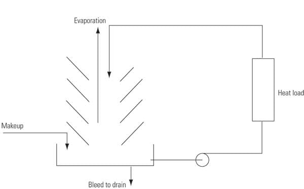
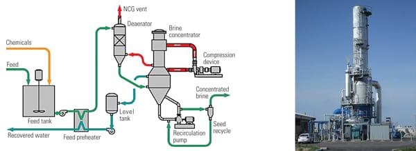
Figure 1 provides a relatively simple solar plant water system process flow diagram. It demonstrates that even “simple” water systems for a CSP plant can be extraordinarily complex.
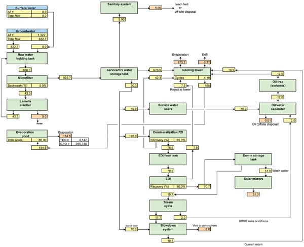 |
| 1. Conceptually simple, practically complex. A relatively “simple” CSP water treatment system can still be complex. These water treatment systems, because of their typical location in arid climates with poor makeup water, are often much more complex than systems for a typical thermal power plant of like rating. The average annual water balance of the example CSP system is illustrated. Yellow boxes represent water flow rates; orange boxes represent water losses from the system. Source: WorleyParsons |
In general, no special pretreatment is needed, provided that the plant makeup water quality allows cooling tower operation at six cycles of concentration or higher and also allows reverse osmosis (RO) systems to operate at 60% recovery or higher. Operation as low as four cycles of concentration in the cooling tower may be acceptable, depending upon land availability for evaporation ponds and the cost of such ponds.
If influent treatment is required (lime softening or ion exchange softening, for example), then the plant capital and operating cost estimates should be adjusted to reflect the increased manpower required to operate these systems. Industry experience has clearly found that one full-time operator must be dedicated solely to water treatment systems if makeup pretreatment or any form of ZLD is used.
Membrane filtration (microfiltration, ultrafiltration, or nanofiltration) should be used any time plant makeup water is provided by either surface or recycled water. These waters typically contain large concentrations of extremely small particles that do not coagulate well. Traditional multimedia filtration cannot consistently remove these particles. Membrane filtration can remove these particles and protect downstream equipment. Potable and well waters typically do not require membrane filtration.
Influent demineralization, which is cost prohibitive for most fossil plants, may make economic sense for CSP plants with an evaporation pond. Demineralizers are generally reliable and relatively simple to operate. They remove all cations and anions, unlike simple softening with ion exchange or lime. The waste stream produced by demineralizers is concentrated and can be sent directly to the evaporation pond. Demineralizing half of the incoming water would lower the concentration of all ions by half, thus doubling allowable cooling tower cycles of concentration and increasing allowable RO recovery. A detailed economic analysis should be performed, but up-front demineralization usually provides an excellent option for air-cooled plants. Most of the water used in air-cooled plants is for steam cycle makeup and mirror washing, so the majority of water required has to be demineralized in any case.
Always try to avoid complicated serial water treatment processes. Lime softening followed by RO followed by demineralization may make sense in a fossil plant, but it may be more trouble than it’s worth in a CSP plant. CSP plant water usage is generally lower than in a similarly sized fossil plant (because dispatch is lower), so operating cost doesn’t increase as much as might be expected when simpler but less-efficient processes are used. Simpler designs normally have a lower capital cost.
New and emerging technologies often show great promise with significant potential savings in water and dollars, but the process risk can be extremely high. Though new approaches may provide benefit, any design that incorporates new technology should include redundancy or contingency to mitigate the higher process risk.
Balance Water Quality and Availability
Solar thermal plant locations exhibit remarkable commonality. They’re typically located in extremely hot and arid environments far from urban areas and other infrastructure. Water is universally scarce. Groundwater and/or surface water may be available, but neither may available in sufficient quantity to meet plant water consumption needs. Water quality data is often nonexistent, particularly its potential for scale and corrosion. Often, the only option for water is drilling new water wells. Water sources and supplies may have to be mixed and matched.
New groundwater supplies must be sampled early and often. At least one and preferably multiple test wells should be drilled and sampled monthly for at least a year. Too many water systems have been designed based on a single unrepresentative sample only to result in deficiencies in the water treatment plant operation. Further, the aquifer must be modeled to determine the potential for change over the life of the plant.
For example, at one CSP plant location groundwater quality was relatively good, but other businesses held significant water rights that had not been exercised in recent years. Aquifer modeling determined that groundwater quality would remain stable, assuming that the current extraction rates were maintained and the new CSP plant demands were added, but water quality would deteriorate significantly if other users began to withdraw at their maximum allowable rates. If such situations occur, a plant can be designed for the current water quality, but provisions must be made to add additional treatment equipment in future years if other users increase extraction. That includes additional building space, underground piping, evaporation pond space, and so on.
Recycled water or degraded surface water (usually agricultural run-off or something similar) may also be available. Though data may exist for the original source water, data rarely exists for the actual recycled water or degraded surface water. Sampling becomes even more critical in such cases because these waters often exhibit significant seasonal variability.
The design water quality for each water source should be determined by calculating the average and standard deviation of all sample results. The design water quality becomes the average (mean) plus two standard deviations for each constituent. This approach provides the additional design margin necessary to account for historical variability.
In addition, water chemistry must be modeled for each potential water source and for mixtures if the plant intends to use more than one water supply. Mineral solubility and chemistry modeling must be performed. As stated earlier, accurate prediction of water usage is especially important in thermal solar plants. Mineral solubility and chemistry modeling determine key water quality constraints that significantly impact plant water usage.
Watch That Water Chemistry
Detailed mineral solubility analysis and a detailed plant chemistry model are critical during the water system conceptual design phase. Water balances too often focus on simply balancing mass or water flow. Chemistry creates many operating and design constraints, including cooling tower cycles of concentration, RO system recovery, and equipment materials of construction. Simply balancing mass is an invitation to disaster because it doesn’t point to the increased risk of corrosion, scale formation, and fouling.
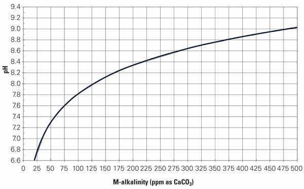
There are many mineral solubility programs available in the marketplace, and most specialty chemical suppliers have been trained in their use. Designers must either educate themselves or get expert advice early in the design process. There are also a number of computer programs available that can evaluate the risk associated with corrosion and scale formation based on makeup water chemistry, cycles of concentration, pH, and product dosage. Most of these programs also include treatment options for specific scales. Figure 2 shows the potential for calcite formation of a typical recycled water source without treatment.
Calcite is just one of many scales that should be modeled to determine treatment requirements and operating constraints. Once all of the common scales have been modeled, the mineral solubility analysis sets the broad range of operating conditions and chemical treatments required. Table 3 provides an example of the operating constraints based on the mineral solubility analysis of the makeup water profiled in Figure 2.
 |
| 2. Calcite saturation at seven cycles of concentration in a cooling tower. The blue columns indicate that no scale should form; red indicates a significant risk of scale formation. When the same water is treated with a calcium carbonate dispersant, all of the bars are blue. Source: WorleyParsons |
 |
| Table 3. Summary of cooling tower water treatment operating constraints. Source: WorleyParsons |
There’s still risk if the mineral solubility analysis is based on nonrepresentative samples. As stated earlier, potential makeup waters should be sampled multiple times if no historical data exists. The mineral solubility analysis should be performed initially, but it should also be updated as more data becomes available.
Minimize Wastewater Treatment
There are a host of possible options for any power plant wastewater discharge: direct discharge to some outside receiver, such as a publically owned treatment works (POTW); direct discharge to the environment (Clean Water Act National Pollutant Discharge Elimination System [NPDES] permit required); deep well injection; direct discharge to evaporation ponds; wastewater concentration with discharge to evaporation ponds; and wastewater concentration to dryness (ZLD).
The lack of local infrastructure usually eliminates the POTW option for CSP plants. Likewise, the lack of suitable receiving water often eliminates the NPDES option. Deep well injection, however, is often overlooked as a viable option. This option requires a suitable aquifer for wastewater reinjection. The capital cost is moderate—more expensive than POTW but less expensive than ZLD or evaporation ponds. The process risk is moderate (multiple injection wells lower process risk, but there’s no absolute guarantee that the well will work), but the simple technology requires very little operator involvement. Deep well injection should also be investigated if ZLD or evaporation ponds in any combination are anticipated.
As mentioned earlier, CSP plants tend to be located in hot, dry locations. The evaporation rate tends to be very high and annual precipitation low. Evaporation ponds are an attractive option provided that land is available. Evaporation pond size decreases as wastewater influent flow to the pond decreases, so wastewater concentration systems can significantly lower pond size and cost. However, larger ponds may actually cost less than the wastewater concentration equipment. Pond cost varies widely, depending on environmental constraints, location, and pond type.
If the cost of larger ponds is within 20% of the cost of wastewater concentration equipment, then discharge directly to ponds. Wastewater concentration systems are complicated, suffer from high operating cost, use significant auxiliary power, and require additional manpower.
If wastewater concentration is necessary, then keep the wastewater concentration system as simple as possible. Avoid wastewater softening, filtering, and RO systems. These technologies can be wonderful options, but they always increase complexity. Simple concentration systems tend to be more reliable and easier to operate. No plant manager or operator has ever complained that water treatment is too simple.
Simple wastewater concentration systems generally consist of one or more evaporators (brine concentrators). These systems can typically increase total solids (the sum of dissolved and suspended solids) in wastewater to approximately 20% to 25% with total dissolved solids of 12% to 17% and total suspended solids of 3% to 8%. Cooling tower blowdown total solids typically average 0.3% to 0.8%, with a maximum of about 1.0%.
Evaporators recover almost all of the unconcentrated plant wastewater and return relatively pure water. The concentrated water decreases in volume and increases in total solids. Increasing total solids from 1% (the maximum in cooling tower blowdown) to 20% (in evaporator blowdown) reduces wastewater volume by a factor of 20. For example, sending cooling tower blowdown with a flow of 100 gallons per minute (gpm) through an evaporator would result in a concentrated wastewater flow of just 5 gpm and would also provide 95 gpm of high-purity distillate suitable for reuse. That means an evaporation pond sized for 100 gpm could decrease in size by a factor of approximately 20.
Evaporation pond size can decrease further through the judicious recycling of low–total dissolved solids (TDS) wastewater. Any wastewater stream with a lower TDS than the cooling tower circulating water should be returned to the tower as makeup provided that it’s acceptable for that use. Oil-water separator effluent and quenched boiler blowdown are commonly discharged directly to an evaporation pond, but both can be used as cooling tower makeup.
Evaporation to dryness without an evaporation pond requires at least two additional steps: thermal crystallization and liquid/solids separation. These systems exhibit extremely poor reliability and extremely high operating cost, and they require heavy operator involvement. They should be avoided if possible.
Air-Cooled Plants Are Special
Air-cooled plants use much less water, but they also present some special challenges. Quenched boiler blowdown, discussed above, is approximately 116 gpm in the model shown in Figure 3. This relatively pure water would normally be used as cooling tower makeup. Lacking a large cooling tower, the Figure 3 model instead routes this flow to the auxiliary cooling system wet surface air coolers (wet SACs). (For more information on the design and application of wet SACs, see “Wet Surface Air Coolers Minimize Water Use by Maximizing Hear Transfer Efficiency” in the September 2008 issue.)
During summer operation the wet SAC evaporation rate is relatively high. The wet SAC can receive virtually all of the quenched blowdown as makeup. During winter operation (as shown in Figure 3), however, the wet SAC evaporation rate lowers, and it cannot receive all of the quenched boiler blowdown. This is good-quality water, low in TDS, and could be used as RO system feedwater. Quenched blowdown is hot, however, so routing it directly to the RO feed tank would certainly cause damage to the mixed bed ion exchange resin downstream of the RO and could cause damage to the RO itself. The blowdown must be cooled before it’s used as RO feed. An air cooler was added for winter operation. Ambient temperatures are lower, so the air cooler provides adequate cooling of the blowdown during the winter. Summer operation doesn’t require an air cooler because the wet SACs can receive all of the quenched blowdown as makeup.
 |
| 3. An air-cooled CSP plant water management system, winter design case (monthly average data). In winter, the two air-cooled towers can’t process design boiler blowdown flow rates. The addition of an air cooler allows this low–total dissolved solids water to be redirected to the reverse osmosis system. Yellow boxes represent water flow rates; orange boxes represent water losses from the system. Source: WorleyParsons |
Although this seems like a small change, it’s important to remember that small water volumes are extremely important in air-cooled plants—much more important than in water-cooled plants. The evaporator in this design is sized to process approximately 100 gpm of wastewater. The evaporator would have to be twice that size if boiler blowdown were not reused within the plant.
It’s important to note that modeling the average annual thermal design case would not detect this unique design requirement that occurs only during the winter months. Wet SAC evaporation rate is high enough to allow the use of all boiler blowdown as wet SAC makeup during average annual ambient conditions, obscuring the problems during winter operation. Once again, the traditional “annual average” thermal design case should not be used to estimate water usage in an air-cooled plant; instead, use the month-by-month method.
A water balance and thermal design is case specific to each month of the year, so avoid design and water plant sizing problems by estimating water usage and wastewater discharge for each month of the year.
— Daniel C. Sampson (dan.sampson@worleyparsons.com) is a water/wastewater engineer in the WorleyParsons Sacramento Office.