Lakeland Electric’s C.D. McIntosh, Jr. Power Plant is a microcosm of the entire power generation industry. On a single site is a once-baseload coal-fired plant that is now operating fewer hours plus a peaking gas-fired combined cycle plant that has swung to baseload operation. A complete controls upgrade of the gas-fired plant last year prepared the plant for its expanded role in producing electricity for this 108-year-old public power provider.
Lakeland Electric, the public power arm of the City of Lakeland, Fla., since 1904, serves 100,000 customers in a 255-square-mile area surrounding the central Florida city, located between Orlando and Tampa. Low-cost electricity is the name of the game for Lakeland. The utility features the lowest rates for small and big businesses in Florida and has the third-lowest residential rates in the state.
Lakeland relies on two power generation complexes for most of its electricity: the 130-MW Larsen Power Plant and the 982-MW C.D. McIntosh, Jr. Power Plant (MPP). Both plant sites are located on Lake Parker in Polk County.
Lakeland is a member of the Florida Municipal Power Pool (MPP), along with Orlando Utilities Commission and the Florida Municipal Power Agency’s All-Requirements Project. The MPP is not a capacity pool but an energy pool that centrally commits and dispatches all the pool members’ generating resources in the most economical manner to meet the pool’s total load requirements. However, each member of the MPP remains responsible for planning and serving the electricity needs of its service territory and for maintaining system reserves sufficient to meet the Florida Reliability Coordinating Council reserve requirements.
Technology Trifecta
MPP features three different power generation technologies. Unit 3 is a nominal 365-MW coal-fired conventional steam plant that burns blends of Central Appalachian and Illinois Basin coals; it has also burned small amounts of refuse-derived fuel mixed with coal in past years. The unit, 40% owned by the Orlando Utilities Commission, was one of the first scrubbed, zero-discharge coal units in the nation when it entered service on September 1, 1982. Gas- and oil-fired Units 1 (90 MW) and 2 (110 MW) were commissioned in February 1971 and June 1976, respectively (Figure 1).
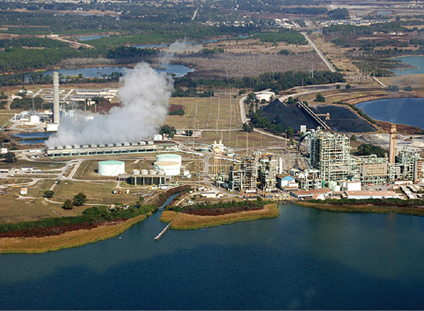 |
| 1. Three technologies. The 982-MW C.D. McIntosh, Jr. Power Plant consists of coal-fired Unit 3 (right), the gas- and oil-fired Units 1 and 2, a 365-MW combined cycle plant (left), and (not visible) 20 2.5-MW EMD diesel engines used for emergency peaking. Courtesy: Lakeland Electric |
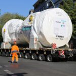
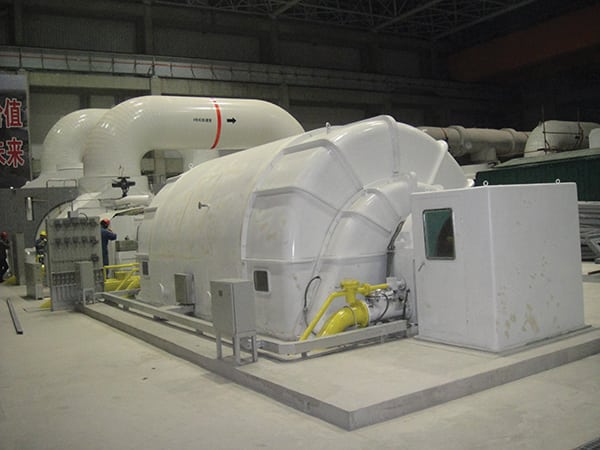
Advanced combined cycle technology is also used at the MPP. In 1999, construction of the simple cycle combustion turbine (CT) portion of Unit 5 began, and the unit was released for commercial operation in May 2001. You may recall that the 501G uses 1,050F steam from the heat recovery boiler to cool the ceramic barrier coated transitions at the exit of each combustor. A temporary package boiler supplied steam for the turbine’s steam needs during initial simple cycle operation (Figure 2).
 |
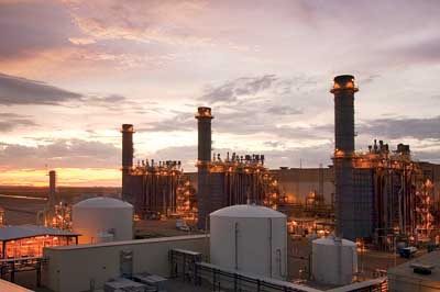
| 2. New lease on life. With low gas prices, the combined cycle unit has assumed baseload responsibilities from the coal-fired units. To the right of the concrete stack is the heat recovery steam generator (HRSG) with selective catalytic reduction and ammonia injection. At a right angle to the HRSG and W501G combustion turbine is the bypass stack. The 125-MW steam turbine is located in the building in the background. Courtesy: Lakeland Electric |
The conversion from simple cycle to combined cycle began in September 2001 with the addition of the waste heat boiler and a 120-MW steam turbine. Construction was completed in the spring of 2002 with the fully operational combined cycle plant declared commercial in May 2002. To meet emerging air emissions rules, during 2009, Lakeland Electric installed an ammonia injection system and selective catalytic reduction on Unit 3. The rating of the completed combined cycle plant is 346 MW summer and 365 MW winter.
The third power generation technology used at MPP is the diesel-fueled peaker engine. Lakeland Electric uses 20 remotely operated EMD 20-cylinder reciprocating engines driving 2.5-MW generators during system emergencies.
MPP Unit 5 features the first Siemens Power Generation W501G combustion turbine (CT) installed in the U.S. Today, the fleet totals 24 units. When purchased, the W501G was configured with a Westinghouse Distributed Processor Family (WDPF) distributed control system (DCS). The WDPF system was subsequently expanded when the steam bottoming plant was added in 2002.
By the time Unit 5 was built, the WDPF system, first released in the mid-1980s and updated to WDPF-II in the mid 1990s, was a mature product that was rapidly approaching obsolescence. Replacing cards that were no longer manufactured was problematic, and the cost of parts when available was quickly rising. Just as significant, some of the processors were operating at maximum capacity. By 2010, WDPF was in need of immediate replacement. The operating reliability of the entire plant now hinged on the performance of a 25-year-old control system.
Project Gets Commission Approval
Approval was received from the City Commission in early 2010 to replace the obsolete Unit 5 control system with a modern DCS. Siemens, the CT original equipment manufacturer, was the natural choice, given its intimate knowledge of the W501G and its integrated plant operating requirements and strategies. The Siemens SPPA-T3000 is also the only control system that has been retrofitted to an existing W501G. With City Commission approval in hand, plans were quickly made for Siemens engineers and technicians to install the new DCS during the already scheduled October/November 2010 Unit 5 outage.
The DCS replacement strategy took two paths: upgrade the software and minimize the hardware changes required. The software upgrades began by ensuring that the entire list of Siemens turbine technical advisories and function logic software upgrades were installed with the new DCS. For example, the new DCS includes 2-out-of-3 logic improvements for the CT speed signals that were not available with the old DCS.
The Siemens engineers began the software upgrade by using the latest reference functional software release for the W501G and the steam turbine governor control. Next, a one-to-one logic conversion was completed based on the actual balance-of-plant equipment and steam turbine auxiliary systems managed by the old WDPF software. To ease the hardware transition in the field, the controls engineers reused the existing tagging system for all hardwired input and output (I/O) signals and those signals transferred to the existing PI plant historian.
Unlike the software upgrades that are invisible to the operator, the monitor screen graphics used by the technicians to operate the plant are personalized to meet the plant’s unique needs. Siemens duplicated the dozens of existing graphical screens of the human-machine interface so well that it took a sharp eye to recognize the differences. Many additional graphic monitoring and alarm screens on 24-inch monitors were added once the operators became familiar with the significantly increased capabilities of the T3000 DCS (Figure 3).
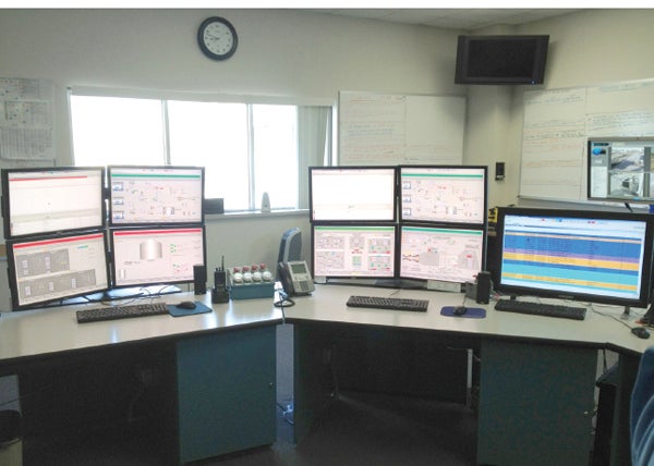 |
| 3. Operator interface upgraded. The DCS upgrade used the graphic designs from the earlier system to accelerate operators’ familiarity with the new system. Suggestions from the staff, based on almost a decade of operation, were also used in the upgraded DCS design. Source: Lakeland Electric. |
Field hardware upgrades began with Siemens technicians removing all the old cards and then stripping the remaining equipment from the cabinets, with the exception of the original card-edge connectors and card-edge connector wiring. The hardware upgrades were configured such that the new processors, I/O, and other PROFIBUS modules could be used in conjunction with the original card-edge connectors to minimize wiring changes from the field instrumentation to the cabinets. The new I/O modules were tied to the original field wiring by plugging the existing card-edge connectors onto a Siemens-designed interface card.
A subcontractor simultaneously ran the new cabling between cabinets and the control room and all the (thin client) HMI control stations. A web browser installed on each thin client provides the user interface hosted by the DCS Application Server. Each management, maintenance, operation, or engineering station has a view of all aspects of plant control and monitoring, although access can be determined by role. SPPA-T3000 applications are hosted by a fault-tolerant application server with a dual-redundant architecture that eliminates single points of failure and safeguards data integrity (Figure 4).
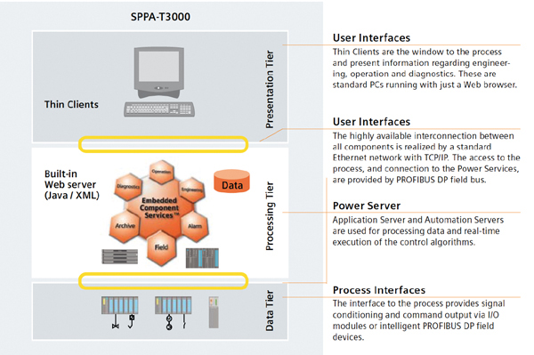 |
| 4. DCS overview. The DCS upgrade can be visualized as consisting of three layers. The field terminal cabinets retained their original WDPF card-edge connectors and field device wiring. A central application/automation server was added that communicates with the HMI user interfaces in the control room via redundant Ethernet cables. Thin client workstations connect to the server using a web interface. Courtesy: Siemens Power Generation |
With the field wiring updated and new DCS cards and components in place, Siemens personnel efficiently made the hardware conversions and performed I/O andloop checks on the combustion and steam turbine trip and protection systems. The subsequent plant startup of the completed DCS was completed without incident (Figure 5). However, the team had to overcome a number of challenges to complete the project on time (see sidebar).
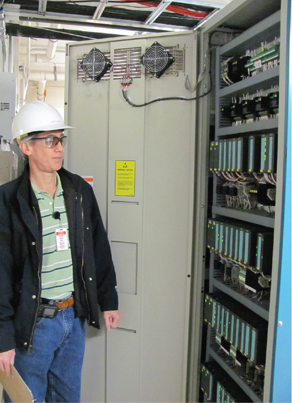 |
| 5. Quick cabinet retrofit. The existing field termination cabinets were stripped and restocked with new control hardware, significantly reducing the time required for the retrofit. Electrical & Controls Engineer Scott Fowler noted that a new optical cable was run across the plant to link all the remote cabinets together with the control room. Source: POWER |
Twelve Lessons Learned
In a discussion with POWER during a plant visit in January, Power Production Operations Manager Kevin B. Robinson, Electrical & Controls Engineer Scott Fowler, and Senior MCO Mark Penix (Figure 6) suggested a number of lessons learned that will surely be of interest to those considering a similar DCS upgrade project in the future:
 |
| 6. Learn from the experts. In a January discussion with POWER, Electrical & Controls Engineer Scott Fowler (left), Power Production Operations Manager Kevin B. Robinson (center), and Senior MCO Mark Penix (right) shared a number of lessons learned. Source: POWER |
- Don’t underestimate the amount of work required to start up the heat recovery steam generator (HRSG) controls. It was our experience that the hardest part of the field retrofit was the HRSG, particularly tuning of its control loops and processes. The drum bypasses were also particularly difficult.
- Three people were assigned to the factory acceptance test (FAT) checkout team: Fowler, Senior MCO Russ Horne, and Senior Controls Specialist Joe Ferro. That was sufficient during the five-day combustion turbine (CT) control system design review at Siemens’ Orlando facilities and five days at the Siemens Alpharetta, Ga., T3000 DCS facility that covered the remainder of the plant equipment and systems integration. However, the three-man startup team was insufficient when the checkout of the controls became the construction critical path.
- Ensure that you have compiled lists and setpoint settings for all the existing trips, unloads, and runbacks (TURs) of the original control system prior to the FATs. Because the CT vendor begins with a “generic” specification, you may find that you have more TURs than you had with the original system. You may not want all the suggested TURs, and you can usually have them removed in advance of the FAT. We also had to remove/override a few modified runbacks during the commissioning process.
- Compile a list of all your steam drain valve setpoints and dead-bands. During steam plant startup, cycling drains can wreak havoc on drum levels and plant stability.
- Perform loop checkouts from the field through the control system to the human-machine interface (HMI), and validate proper response and ranges for every input and output (I/O). We found several reversed analog loops and digital I/O points during plant commissioning.
- Ensure your engineers or technicians work with the distributed control system (DCS) supplier while calibrating the hydraulic servo valves and the inlet guide vanes. You will not be able to do this in the future unless you develop procedures during commissioning checkout.
- Ensure that the startup work schedule is agreed to in advance, as hot commissioning of the DCS is likely to occur at the end of the outage. For example, will commissioning be a 24-hour-day process or limited to 12-hour days? If longer than 12 hours each day, you may want two crews of vendor engineers and two crews of owner engineers/technicians. Mirror commissioning shift-change with the production department’s schedule, or there will be dead time during multiple shift changes.
- Purchase enough site licenses. We have five HMI stations, and when all HMIs are in use, we are unable to remotely log in to our system via the Microsoft Terminal Server. Also, if the vendor fails to properly “log out” from the system after remotely dialing in, our personnel are unable to utilize our fifth operating station. I recommend that you purchase one or two extra licenses in addition to the number of HMIs purchased.
- Keep the same basic graphical display on the HMI as you currently use to quicken operator transition to the new system. One way to do this is to screen copy each of your current graphic screens and provide copies to the DCS vendor early in the project. Include a plant master screen and the switchyard, if not already included in the original DCS screen design. Require the vendor to return samples of the new HMI screens as soon as possible in order to correct errors prior to the FATs. Finally, get copies of the AutoCAD system files for your files.
- Send those members of the operations and controls staff with the deepest understanding of plant operations, who are proficient in reading logic diagrams, to each FAT. Empower that team to make control and graphic changes to fit your operations culture and preferences. Encourage the team to customize the menus, add navigation shortcuts, or do whatever will improve the efficiency of operations.
- Check and confirm that alarm designations and priorities between the combustion turbine portions of the DCS design are consistent with those used on the remainder of the plant. This would have been confusing to the plant operators had it not been caught and corrected during the FATs.
- Check and confirm that the labels and colors used to designate valve and controller position are consistent between the CT and remainder of the plant portions of the HMI design.
—Contributed by Power Production Operations Manager Kevin B. Robinson
Also completed during the “double major” outage of the combustion and steam turbines was a major inspection of the W501G gas generator (at 47,468 hours) so the heavy mechanical portion of the outage was the outage critical path. However, as the mechanical work reached about the 80% completion point, the critical path predictably shifted to the controls upgrade work, forcing the controls team to work around the clock for several days to maintain the aggressive outage schedule.
Highly Anticipated Results
One year after the DCS upgrades were completed, Unit 5 is now operating baseload as the utility’s lowest cost generator, rather than cycling offline every three days or so, as in past years.
A new low-load turndown capability was also added during the DCS retrofit. The combined cycle plant, originally able to operate within emissions limits down to 50% of CT baseload, now has the capability to operate down to 30%. Unit 3 (the coal-fired unit) is able to cycle down at night to about 50% load. Together, the wide operating range of both units provides Lakeland Electric considerable operating flexibility when meeting its MPP commitments.
During the summer of 2011, Unit 5 operated continuously for 122 days until it was knocked off-line by a lightning strike that damaged the voltage regulator, air emission monitor, and other equipment. After a one-week outage for repairs, the combined cycle plant resumed baseload operation. As of mid-April, the 2012 YTD equivalent availability factor was 82.7%, which includes a combustor inspection outage, and the equivalent forced outage rate was only 1.43%.
The plant heat rate is much improved with the installation of a new CT turbine rotor and DCS in 2011. During and prior to 2010, the plant heat rate was approximately 7,000 Btu/kWh. The plant heat rate today is about 6,740 Btu/kWh. The 2011 gross average heat rate was 6,606 Btu/kWh.
— Dr. Robert Peltier, PE is POWER’s editor-in-chief.