When a power plant experiences issues with performance, the obvious indicators are usually a loss in load capacity or an increase in fuel consumption. However, other issues exist that can be costly, such as turbine cycle performance problems, which are difficult to detect because of existing instrumentation limitations and insufficient plant monitoring points. That’s why it is important to regularly test steam turbine cycles to maintain a quality reference for future performance changes.
 |
|
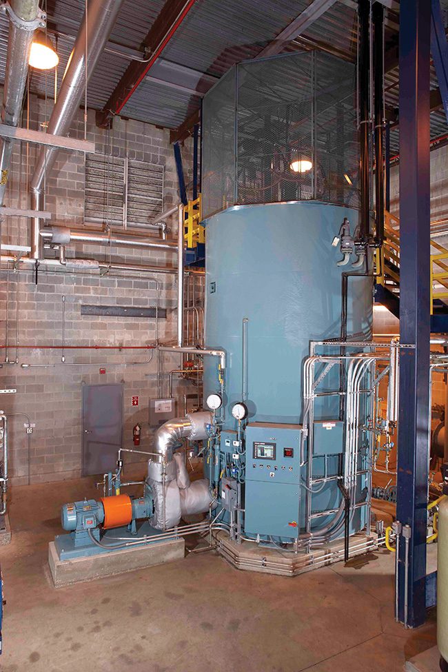
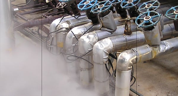
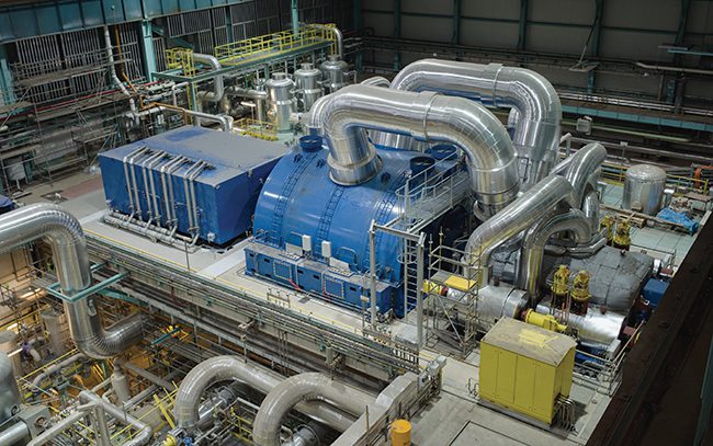
1. Testing of steam turbines and generators, such as this equipment in a coal-fired power plant, is important to identify potential operating issues and maintain optimal performance. Courtesy: GSE Solutions |
Successful programs track thermal performance test data through annual capacity tests like the American Society of Mechanical Engineers (ASME) Performance Test Code (PTC) 6 for fossil and nuclear-fueled utility-grade steam turbines/generators (Figure 1). PTC 6 is the international standard for steam turbine acceptance testing, which provides a consistent method for determining existing, retrofitted, and new steam turbine performance within the minimum practical uncertainty.
Several steps can be followed to create a performance plan for your plant using the procedures of PTC 6. The plan includes identifying corrections, test planning, evaluation of the turbine, and reporting. Doing so will identify maintenance issues early to keep the plant from potential performance losses.
Identify Corrections
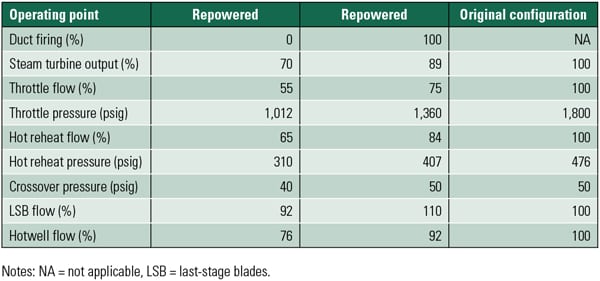
The first step is to create the foundation with a heat balance diagram (HBD). Using a representative HBD of the turbine generator cycle and the correction curves included in the original equipment manufacturer’s thermal kit, the load and heat rate can be corrected to design and compared to their respective values on the representative HBD. Changes to the corrected load, or any correction component, will indicate a deficiency or improvement in cycle performance.
Corrections are broken into two groups: Group 1 for variations in cycle parameters and Group 2 for steam or boundary conditions (see below). These corrections are meant to calculate the effect of off-design steam and cycle parameters for comparison to the design.

In This Issue
Full issueCycle heat balance software can be used to develop additional or alternate correction curves per the objectives of the test. This can be especially useful if the plant arrangement differs from the design HBD.
Here are examples of Group 1 corrections:
■ Heater terminal temperature difference (TTD).
■ Heater drain cooler approach (DCA).
■ Extraction line pressure drop (ELPD).
■ System water storage changes.
■ Condensate subcooling.
■ Makeup flow.
Here are examples of Group 2 corrections:
■ Throttle pressure.
■ Throttle temperature (or quality).
■ Reheat temperature.
■ Reheat system pressure drop.
■ Low-pressure (LP) exhaust pressure.
The corrections are parametric components whose product is applied to the test load and tested heat rate, which then gives the corrected load and heat rate. The corrected load and heat rate can then be compared to the HBD to determine how the plant operates relative to the design.
The corrections listed are the minimum required for a PTC 6 alternative test. LP heater corrections have minimal impact on overall performance and are typically neglected for the alternative test, and therefore, not listed in this example. Corrections with the most impact are throttle flow (or thermal power), LP turbine exhaust pressure, reheater pressure drop, and feedwater temperature.
Special attention to these measurements is critical for quality test results. Throttle pressure correction can be significant for a control stage machine, or effectively zero for a full-arc admission design with a separate flow correction. Heater performance corrections are usually smaller, given that the test parameters are close to the reference and decrease in magnitude significantly through the lower pressure zones. The test plan can vary from the code with the parties’ agreement and should be tailored to the specific goals of the plant.
In addition to load and heat rate, cycle pressures can be corrected to the ratio of test flow divided by reference flow to compare the pressure-flow relationships of the various turbine sections to design. Over sequential yearly tests, flow-corrected pressure can uncover issues with deposits, cylinder leakages, or solid particle erosion.
Records of corrected load, heat rate, cycle pressures, and heater performance parameters should be tabulated following each test to track variations over time. This data can be used to build a trend that helps diagnose issues that arise. Performance test tracking is also useful for determining degradation over time for maintenance or baseload dispatch planning. It is often executed yearly, or biyearly.
Test Planning and Methods
The testing method should be defined before the turbine is installed. The plant should start planning months ahead of a performance test. Test preparations may require outage work scope to be added. Some timing limitations associated with test planning include identifying test points that need service, procuring test instrumentation, inspecting basket tips in the condenser for LP exhaust pressure, and seasonal considerations for attaining the desired condenser pressure.
 |
|
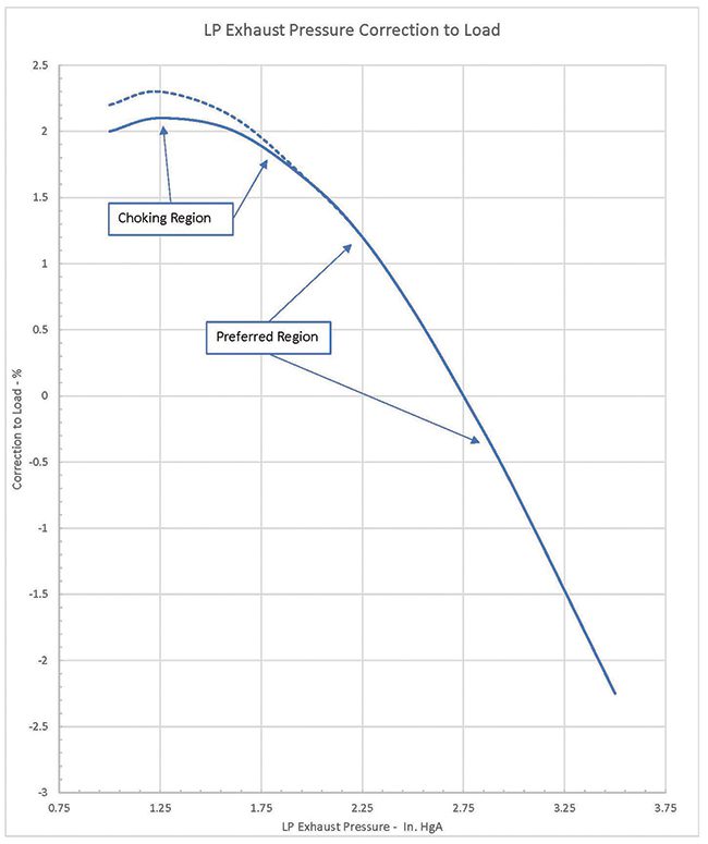
2. This chart provides a reference for a low-pressure (LP) exhaust pressure correction curve. Courtesy: GSE Solutions |
If the reference condenser pressure is not practical in normal operation, the LP exhaust pressure correction curve should be referenced and testing planned around operating in the more linear portion of the LP exhaust pressure correction curve (Figure 2) to avoid the choked region. Often, condenser basket tips are loose or missing, so planning prior to an outage is advantageous. An outage also presents the opportunity to exercise any root or instrument valves that aren’t frequently used.
Here are some important aspects of the testing process:
■ Instrumentation.Test instrumentation should be test-quality and calibrated to National Institute of Standards and Technology (NIST) traceable standards. Temporary test instruments and redundant measurements should be used where primary corrections are to be applied. Some examples are main steam and reheat pressures and temperatures, primary flow pressures, and LP exhaust pressure. These high-quality measurements will minimize the error in corrections, steam table references, and comparison to the HBD. Temporary instruments can also be a reference point for plant instruments used in normal operation.
■ Cycle Isolation.Cycle isolation must be established before the test. Isolation is meant to confine the turbine generator to only include the flows shown on the HBD via the prepared valve lineup. Flows outside of what is shown on the HBD and unable to be isolated must be measured or estimated and a correction applied based on its sensitivity to load and/or heat rate. Typical isolation points include main steam bypass, blowdown, unit cross ties, and makeup. Cycle water loss is measured by hotwell drop and storage tank level changes.
■ Operations. The unit should operate at full load and stabilize within the acceptable deviations from the reference conditions before the test. Fossil machines typically require operation at valves wide open (VWO) for the test, but nuclear plants often cannot test at VWO due to licensed core thermal power limitations. Once stabilized, the unit must maintain the conditions within the acceptable fluctuations throughout the tests. The acceptable deviations and fluctuations are identified in Table 3.1 of the PTC 6 test codes. Test data should be recorded for two hours per test, with at least a one-minute sampling rate, for two test periods and the corrected load (or heat rate) for each test should agree within approximately 0.25%. In many cases, the test period can be adjusted to eliminate data that exceeds the acceptable fluctuations at the beginning or end of the test.
Evaluation of Turbine
Test results can provide useful information for the turbine and other components of the cycle. Flow, pressure, and efficiency are the most important factors for producing power in their respective order of precedence. The magnitude of lost power can indicate what to look for.
When flow is lost, it will be apparent in all turbine sections’ downstream pressures. For example, if the main steam bypass leaks 1% to the condenser, first-stage pressure and LP inlet pressure would be lower by approximately 1%, as would be load. However, if that 1% leak is at crossover, first-stage pressure would be relatively unchanged while LP inlet pressure would be 1% lower and load about 0.5% lower.
The most important indicator of flow through the turbine is the first-stage pressure. The relationship between stage inlet pressure and flow is linear and should correlate within 2% to 3% of the design on the HBD. Pressures can be corrected to the ratio of the HBD flow to the test flow for comparison to the HBD. These are referred to as corrected pressures. Corrected pressure can point out missing flow or damage to the turbine.
In superheated cycles, the measured efficiency of the high-pressure (HP) and intermediate-pressure (IP) turbine sections can be directly determined. VWO isentropic efficiency should be constant across the load range and comparable to the HBD. Using the HBD to calculate the work split among the turbine elements, the load impact can be determined for elements that test below the HBD reference.
Nuclear units operate in the moisture region and efficiency cannot be directly determined. These turbines can use alternate indicators, such as turbine blading pressure ratios and heater drain flows, to monitor efficiency indirectly.
Reporting
Corrected load and heat rate should be plotted over time. Other key parameters that should be tracked are corrected stage pressures, HP and IP element efficiencies, turbine element pressure ratios, throttle flow capacity, and feedwater temperature. Deviations in the parameters between tests can help identify where losses are coming from to help to plan repairs or other corrective actions.
Tests should be performed periodically with a running comparison of key parameters. Keeping quality test records will help identify the cause when issues arise and provide cost-effective data for dispatch planning.
A performance plan for your plant using the procedures of PTC 6 can keep you ahead of performance matters as they arise. These tests can be performed in-house or outsourced to experts. Either way, it is important to identify maintenance issues early and to keep your plant ahead of potential performance shortfalls.
—Dave Cavanaugh Sr. is a project engineer for GSE Solutions.