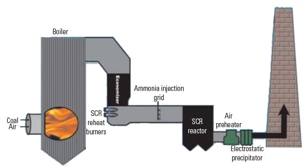
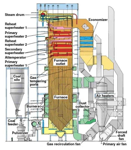
Poor airflow around its selective catalytic reactor (SCR) was causing heavy fly ash accumulation and pluggage at Kansas City Power & Light’s 815-MW La Cygne Unit 1. Flow modeling and redesign of the SCR hood led to dramatically improved conditions and reduced maintenance costs.
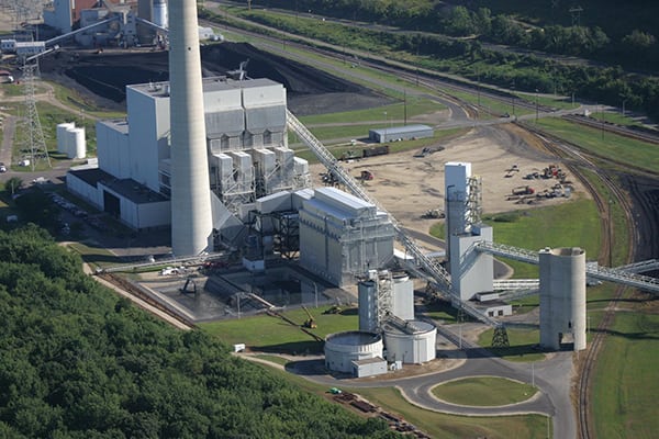
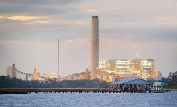
The Kansas City Power & Light (KCP&L) La Cygne Generating Station provides 1,532 MW of peak power from its site south of Kansas City. La Cygne Unit 1 is an 815-MW Babcock & Wilcox cyclone boiler with overfire air and selective catalytic reduction (SCR) nitrogen oxide (NOx) controls. Unit 1 burns a blend of 90% Powder River Basin (PRB) and 10% local Missouri coal.
The unit’s SCR was installed in 2007 with a 3 + 1 catalyst layer configuration, which consists of three initial layers of catalyst with one spare layer for future use. In the fall of 2012, plant staff vacuumed 2,900,000 pounds of fly ash from the SCR after a 17-month operating cycle. This was twice the typical amount of fly ash removed in previous outages because the unit had operated for an extended time with a low demand load factor. However, the catalyst pluggage of approximately 50% was typical of previous operating cycles.
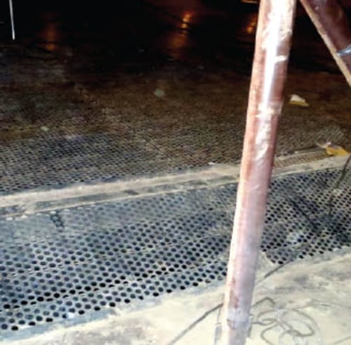
The SCR consists of two reactor casings separated by a common division wall. Flue gas enters the SCR North Side B and South Side A of the SCR hood to flow down through these separated casings. Fly ash would accumulate 5 to 6 feet deep near the SCR north to south reactor casing division wall (Figure 1). The fly ash accumulation caused high ash removal costs, high catalyst replacement costs, high catalyst pressure drop and fan power costs, and high ammonia slip and ammonia reagent costs. In addition, cleaning the catalyst became a critical path activity during outages. The fly ash accumulation also caused unit capacity derates in combination with other draft losses.
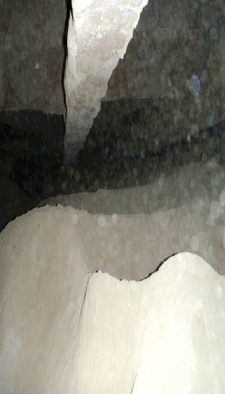 |
| 1. A big problem. Poor airflow was causing heavy fly ash accumulation in the SCR. Here, mounds of ash have built up near the reactor casing division wall. Courtesy: KCP&L |
Many minor changes were attempted through the first five years of SCR operation. These included installation of missing flow control baffles, corrections to the sonic horn, covering or removal of horizontal vane and beam surfaces, and enlarging the honeycomb ceramic catalyst pitch. These minor repairs were not successful, because they were not addressing the root cause of poor flow distribution.
Poor Flow and Many Restrictions
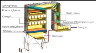
To keep PRB fly ash moving through the catalyst, flue gas flow must be of uniform velocity, vertical, and without recirculation. In 2010, KCP&L La Cygne initiated computational fluid dynamics (CFD) flow modeling with Fuel Tech to determine the cause of fly ash accumulation and correct flow variances to the catalyst. The CFD analysis shown in Figure 2 indicated problem areas, including the following:
■ SCR inlet duct north-south contraction pushed flow to the lower four SCR hood turning vanes.
■ Trusses and large gusset plates in the SCR inlet duct and hood restricted flow to the upper four SCR hood turning vanes.
■ The turning vanes and perforated plate on top of the original egg crate flow-straightening grid created flow recirculation zones that caused fly ash dropout. The turning vanes also collected ash on horizontal surfaces because of low flow, and these ash piles sloughed off during forced draft (FD) fan startups.
■ The egg crate structural support steel created flow disturbances that could not be corrected in the short distance to the first catalyst layer.
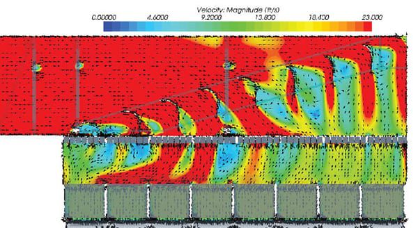 |
| 2. Uneven conditions. This CFD profile of baseline velocity results in the SCR hood area shows widely variable airflow and areas of recirculation behind the turning vanes, resulting in ash dropout. Courtesy: Fuel Tech |
The flue gas recirculated behind the SCR hood turning vanes, but the fly ash did not follow this twisting route and instead fell out on the catalyst layers. Because of these issues, KCP&L decided that the existing flow-straightening devices needed to be removed and replaced with a new design that addressed the findings of the flow model.
The Redesign
Modification of the SCR hood was originally planned for the fall of 2013. However, low demand load factors on KCP&L and Westar systems in 2012, and the high price of continuing catalyst ash pluggage, led to the decision to move the project up for a 2012 installation. A planned boiler inspection outage was extended to accommodate the work. Design of the new flow distribution devices for the SCR hood began in July 2012, with the outage scheduled for October. With the short time frame for design and fabrication, the contracted services were secured for flow modeling, structural engineering, fabrication, and construction installation.
Black & Veatch was contracted to provide design drawings and specifications, review the flow modeling and proposed flow distribution devices, and evaluate constructability. The entire team participated in preliminary flow model result review meetings to provide immediate input to flow modeling and direction to engineering. Probable flow distribution devices were detailed by engineering to obtain construction installation bids. Catalyst installation was planned for Layers 2-3-4 to allow Layer 1 to be a work platform for the SCR hood modifications. Flow device fabrication was performed off-site at fabrication shops to speed production. Fabrication was scheduled to continue through the start of the October outage because demolition would occur before new materials would be needed.
A CFD modeling study analyzed the removal of the SCR hood turning vanes and replacement with Fuel Tech’s Graduated Straightening Grid (GSG) technology. The GSG device consists of parallel plates installed in the SCR hood on the diagonal, to turn the flue gas and fly ash vertically into the first catalyst layer.
GSG technology improves on traditional SCR airflow design in several ways. Until recently, controlling the velocity distribution and flow direction into the face of the first catalyst layer was accomplished with large turning vanes along with a straightening grid placed immediately above the catalyst. The turning vanes were tuned to achieve an even velocity distribution while the straightening grid below straightened the flow direction.
The turning vane system requires exact spacing and angling of turning vanes during SCR construction to ensure required flow distributions are met. This solution is also extremely sensitive to changes to the upstream flow distribution, and any changes to the system require remodeling and retuning of the vanes to maintain the required distributions.
In contrast, the GSG combines the turning vanes and straightening grid into a single sloped grid. The GSG has been shown to be a robust flow corrective solution in a number of previous installations, as it is much less sensitive to upstream flow distributions compared to traditional solutions. This means that the catalyst and catalyst performance are protected even when the unit is not running at optimum design conditions, including economizer bypass operation.
The CFD model results showed that installation of the GSG corrected the large flow recirculation zones, and flow was vertical out of the GSG. However, the flow statistics were not within the project team’s target of +/–15% of arithmetic mean velocity. The SCR hood truss/gussets and egg crate structural steel were creating large flow velocity variances before the first catalyst layer.
The CFD model was reanalyzed, considering three scenarios: removal of the two trusses, removal of the egg crate support steel, and removal of both truss and egg crate. Removal of all internal structures had the best results, but removal of the egg crate steel had a nearly identical result without the expense of replacing the SCR hood truss system. However, the flow statistics were still not close enough to the recommended +/–15% of mean. The SCR inlet flue contraction and truss/gussets were both working to push flow to the SCR inlet corner and away from the back half of the SCR reactor casings at the division wall. The CFD model run was used to tune a variable perforated plate across the leading edge of the GSG blades at several positions. This variable perforated plate prevented excess flue gas from making the quick turn into the front of the reactors and pushed more flow past the truss/gusset system to the back half of the reactors.
The final modification arrangement included demolition of the turning vanes in the hood of the SCR reactors and demolition of the original egg crate flow straightener, perforated plate, and its support steel.
Installation
The conceptual design developed by Fuel Tech in the flow model was then developed into detailed design drawings for fabrication and installation. The GSG blade detail drawing was completed in advance, based on Fuel Tech’s standard design. Engineering added the final perforated plate details and turned these drawings over for fabrication. Engineering also began redesign of the support for the SCR pressure load where the egg crate support steel was removed. The egg crate steel not only supported the old flow straightener weight but also restrained the pressure forces on this elevation. A buckstay arrangement was developed to resist these forces.
The selected arrangement was installation of the GSG device with a perforated plate at the turning vane location. The GSG replaced the turning vane and egg crate functions by turning the flow 90 degrees and aligning the flow vertically to pass through the catalyst layers. A perforated plate was needed on the GSG blades’ leading edge to overcome the low flow at the SCR A and B division wall. The flow statistics did not quite reach the desired project goal of 100% of all flow velocities within +/–15% of arithmetic mean. The final model showed flow distribution statistics with 91% of all analyzed flow velocities within +/–15%, which is equal to 9.5% root mean squared (rms). This was a significant improvement compared to the original, traditional turning vane design where 58% of flow velocities were within +/–15% (17.5% rms). The flue gas flow direction, shown with velocity vectors, was excellent. The flow recirculation was nearly eliminated, except at the two truss systems, and the flow direction was vertical going into the catalyst (Figure 3).
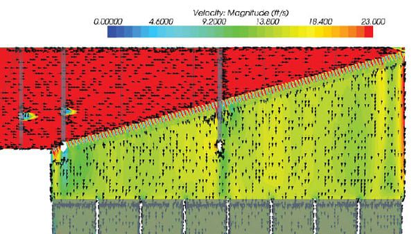 |
| 3. Straight and even flow. The new design produced vertical, non-recirculating, uniform velocity to the catalyst. Courtesy: Fuel Tech |
Fabrication of the GSG modules was straightforward. These modules were completed and shipped to the site prior to installation crew needs during the October outage. The late addition of the variable perforated plate added a complication to the fabrication schedule. Fabrication time at six different shops was secured to laser or plasma cut all the perforated plate parts. The final GSG device with perforated plate was installed as shown in Figure 4.
  |
| 4. Fewer obstructions. The new design is shown from above (top) with the perforated plate, and from below (bottom). Courtesy: KCP&L |
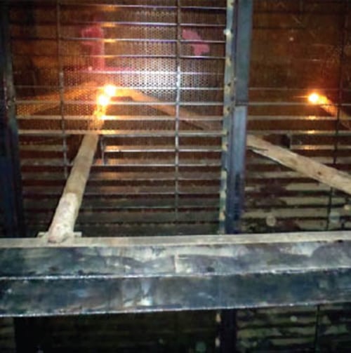
One wrinkle was that the egg crate steel above the Layer 1 catalyst had included the catalyst removal cart wheel tracks. As a result, an alternate catalyst installation method needed to be developed. A grating floor was installed in catalyst Layer 1. Future Layer 1 catalyst installation will be by pallet carts. Catalyst was installed in Layers 2-3-4 during the 2012 outage to aid the GSG construction sequence.
Additional fly ash accumulation prevention measures were taken by installing ash guards on all horizontal surfaces inside the SCR. Catalyst support beam teepee ash guards were installed on the grating floor to prevent fly ash stalagmites from growing up from the beams. Catalyst seals were sloped to prevent stalagmite growth, and support beams and loading monorail beam pockets were covered to prevent ash buildup and ash sloughs. SCR hood truss beam pockets were covered, beam tops were sloped to eliminate ash buildup, and beam bottoms were fabricated into airfoils to avoid recirculation zones.
Much Improved
An inspection after four months of operation showed excellent results at the SCR division wall, which was a trouble spot originally. Figure 5 shows much cleaner conditions after installation of the GSG (compare with the Figure 1 shot, taken in the same area before the redesign). These improvements are the results of the GSG technology providing improved flow in the SCR hood.
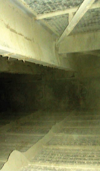 |
| 5. Clean sweep. With the new airflow measures in place, fly ash accumulation was dramatically reduced. Courtesy: KCP&L |
The GSG and perforated plate modifications resulted in more than $5,000,000 in capital cost savings compared to other options, including truss removal and changing the original inlet flue gas distribution design. Reduced fly ash accumulation in La Cygne Unit 1 SCR will reduce catalyst replacement costs, reduce removal costs, reduce catalyst pressure drop and fan power costs, reduce ammonia slip and ammonia costs, and reduce complexity of outages.
The next catalyst layer replacement is not budgeted until after 2019. This will mean that only one layer will need to be replaced after seven years of operation—a major improvement compared to the eight layers KCP&L had to replace over the previous five years. ■
— Scott Hiedeman is senior AQC engineer with KCP&L. Reid Thomas is senior process engineer and Dale Pfaff is mountain regional sales manager with Fuel Tech Inc. Diane Fischer is services area leader, AQC, Energy with Black & Veatch.