Composite materials are ideal for producing wind turbine blades because of their strength, light weight, and ability to be tailored to provide the precise mechanical properties needed for any blade design. Now, best practices originally developed for rotorcraft blade manufacturing can be applied to designing and manufacturing wind turbine blades that are constructed from composites.
Composite materials are well suited for use in the manufacture of wind turbine blades, yet the structural complexity of these materials also presents difficult challenges in optimizing design and manufacturing methods. From a design and manufacturing standpoint, wind turbine blades have many similarities to helicopter rotorcraft blades and other aerospace structures. Wind turbine manufacturers, therefore, have the unique opportunity to adapt and apply the best practices developed and refined over several decades in the aerospace industry and help their businesses succeed in a tough competitive environment by reducing design lead time, improving blade durability, and optimizing design and manufacturing processes.
Composites dominate the wind turbine blade market due to their superior fatigue characteristics and stiffness-to-weight ratio, their unique ability to be fabricated into complex geometries, and their potential for aero elastic tailoring. The ability to tailor composites to specific loads and other requirements is among these materials’ greatest strengths, but it also increases the complexity of the design process.
Challenges of Traditional Wind Turbine Blade Design
Optimizing the properties of the blades is critical to delivering the needed bending strength and fatigue performance while minimizing cost and weight. The properties of composite blades can be tightly controlled and varied over their span through the appropriate selection of ply orientation, thickness, and lay-up. Because high hopes are riding on this alternative energy source, the wind turbine blade industry is working hard to improve manufacturing efficiency and address blade failure issues, but challenges remain great, and failure rates are as high as 20% within three years.
Most causes of failure can be attributed to substandard design and manufacturing practices that could be eliminated by adopting many of the best practices for composites design and manufacturing in the aerospace industry. A significant part of the challenge may be that nearly all composite blades today are designed on basic computer-aided design (CAD) systems intended for making solid metal and plastic parts of far less complexity than today’s sophisticated, multi-layered composites. The limited capabilities of the traditional CAD systems means that analysis and manufacturing engineering are carried out in separate and disconnected environments, creating inefficiencies and introducing the potential for error.
In the typical process, the aerodynamicist first defines the outer shape of the blade using specialized fluid flow software packages and wind tunnel testing. This design is then provided to mechanical engineers, who define the detailed design and basic ply guidelines for the blade. The CAD software has no facility for keeping track of the laminate information involved in composites design, so the engineer typically tracks this information in a spreadsheet.
The engineer might start by defining areas of the part with similar thicknesses or structural zones. The zone information is usually maintained manually in a spreadsheet. Then the engineer will define a ply stack that delivers the mechanical properties required for each zone, as indicated by previous experience. Most companies involved in composite design have design rules that are used to guide this process. For example, the smaller plies may be located on the inside of the stack and the thicker plies on the outside.
An analyst typically creates a finite element model from scratch to evaluate the bending strength and other characteristics of the blade. Various loading conditions are used to simulate different wind conditions. The proposed blade design may be challenged by load-time histories to predict its fatigue strength. The analyst recommends changes to the plies based on the analysis results. The design typically goes back and forth between the engineer and analyst multiple times—all the while being manually tracked via spreadsheet, which has room for error.
The Wind Turbine Blade Manufacturing Process
Defining the manufacturing process comes next. In the traditional approach, the final shapes of the flat patterns are determined on the shop floor by expensive and time-consuming trial and error: cutting plies, laying them onto the molding tool using manual measurement, checking for distortion, re-cutting, and trying again. The complex aerodynamic shape of wind turbine blades makes it hard to predict how composite materials will conform to the mold’s complex surface. Sometimes distortion causes the material to draw away from the mold. In other cases, a ply sequence imbalance across a three-dimensional (3D) shape generates stresses that cause wrinkling or warping. A major difficulty is developing flat patterns that will meet the ply guidelines without fabric distortion, such as bunching up on the mold. Using conventional methods, this process cannot even begin until the molding tool is built.
At this point, the common procedure is to cut fabric plies by hand and try to fit them on the mold tool. Inevitably, a considerable amount of distortion is seen. Assemblers use darts and splices in an effort to solve the problem. The trial-and-error nature of this process means that the material is finally fit to the mold using far more darts and cuts than would be necessary if the flat pattern shapes were optimized, resulting in a weakened final product. It is also not a repeatable process. The flat patterns that result from this process are measured and used for volume production, which means that the waste is repeated on every blade built. The entire first part of the process typically takes large amounts of time and consumes substantial amounts of expensive composite materials.
Applying Lessons Learned in the Rotorcraft Blade Industry
From a design and manufacturing standpoint, wind turbine blades have much in common with helicopter rotorcraft blades. The loading on a wind turbine blade and a rotorcraft blade consists primarily of aerodynamic pressure loads. However, the speed of a wind turbine blade is much slower, so it experiences much lower aerodynamic pressures (Figure 1).
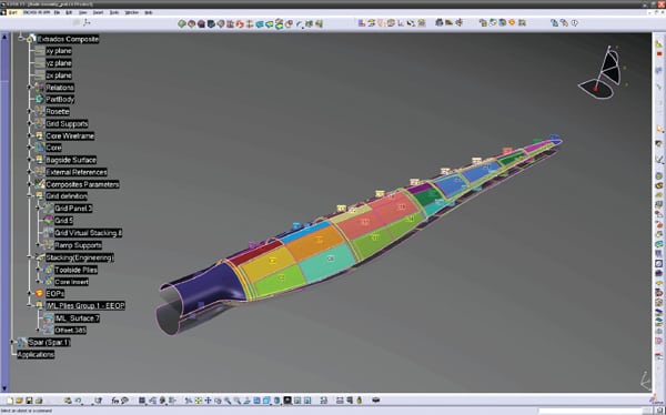 |
| 1. Early input. Starting very early in the lifecycle of wind turbine blade design, the analyst provides the designer with inputs such as stacking sequences or thickness laws. Courtesy: CATIA Composites |
Taking into account best practices learned from the rotorcraft blade industry, Dassault Systèmes developed CATIA Composites Design, a product lifecycle management solution that provides a dramatic improvement over conventional CAD systems by providing a complete end-to-end solution for preliminary design, engineering detailed design, manufacturing detailed design, simulation, and manufacturing export—all on the same virtual platform.
The similarities between wind turbine and rotorcraft blades mean that the rotorcraft blade industry’s best practices can be used to integrate either a structural zone-based modeling into the design environment or a grid-based approach using analysis thickness laws or stacking sequences at the beginning of the lifecycle of the part. Either design approach saves large amounts of data entry time, which can be devoted to more productive tasks and innovation. It also becomes possible to generate conceptual solids to quickly integrate the composites part into the mock-up, enable concurrent engineering with mating parts, and even provide preliminary inputs for tooling to start working on the mold. CATIA Composites Design automatically generates splices from the solid model based on the zone or grid design while keeping full associativity between the plies and solid. It organizes the ply buildup by recording nongeometric information and creating sequence charts per company standards, material tables, and lay-up books.
The ability to virtually design the composite lay-up within the context of the complete blade assembly streamlines the design process. It also ensures a higher level of accuracy that reduces the number of physical prototypes needed to finalize the design. This in turn cuts costs, eliminates trial and error, improves accuracy, improves durability, and minimizes splices and darts. Leveraging powerful design optimization tools provides advantages such as the ability to swap ply edges to optimize drop-offs, shape plies, and re-route sets of plies along a preferred path.
Tighter Integration with Analysis
The new best practices pioneered in rotorcraft blade design substantially improve the analysis process by integrating design with finite element analysis (FEA) for fast design-analysis iterations with the zones and plies definition. Bidirectional communications are provided between design and analysis at both the conceptual and detailed design stages. The ability to directly transfer accurate fiber angles and ply thicknesses from the design to the analysis environment improves the simulation accuracy (Figure 2). The ability to transfer updated design information from analysis back to design enables designers and analysts to work closely together, ensures that the analyzed model matches the final structure, and prevents the specification of plies and structures that cannot be manufactured (Figure 3).
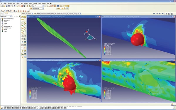 |
| 2. Just a simulation. With SIMULIA’s Abaqus, the analyst can simulate different conditions, such as the high-speed impact of a bird strike. Courtesy: SIMULIA |
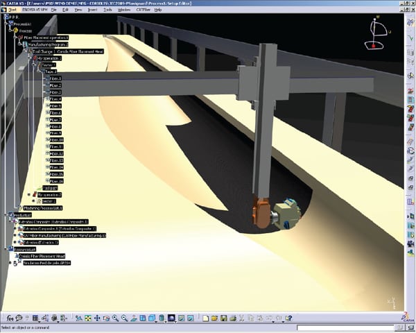 |
| 3. Using the virtual world to make the real world better. Ensuring manufacturability in a virtual environment is key to ensuring that the “as built” model matches the design intent. Courtesy: DELMIA and Corolis |
For example, Abaqus FEA software provides engineers with advanced, state-of-the-art capabilities for simulating realistic composites behavior, including delamination and damage. These complex, nonlinear effects are modeled using cohesive elements and Virtual Crack Closure Technique (VCCT). The VCCT capabilities in Abaqus enable engineers to identify the overall load at which a crack initiates and to predict the behavior of the structure as the crack propagates. It also helps users understand the stability and load-carrying capacity of the composite structure after failure.
Evaluating Manufacturability in the Virtual Environment
Aerospace best practices also provide dedicated features to ensure that the detailed design is manufacturable and to avoid trial and error on the shop floor. The lay-up of the composite plies onto the mold tool is simulated to identify areas where the part geometry will cause fabric distortion. The engineer can then add darts or splices or make other changes to the ply and receive immediate feedback on whether the changes have corrected the design problem.
The program then automatically generates the resulting pattern geometry for each ply within the CAD environment. This geometry can be exported to a ply-cutting machine to produce the patterns for prototyping, saving the time that would normally be spent cutting the patterns by hand. More important, with simulation identifying manufacturing problems in the virtual environment, the first iteration of the design should be correct or very close to correct, eliminating the need for trial and error on the shop floor.
Composites design and manufacturing data can easily be linked to nesting systems, as well as all industry-standard laser projection systems. Depending on the nesting solution, the data can be directly accessed from the CATIA Composites mode. The engineer can further optimize the layout of ply shapes in an effort to minimize material use. Integrating the composites design with laser projection allows the engineer to preview and optimize laser projection on screen before manufacturing begins—an effort to eliminate costly trial and error. It also eliminates the need for manual measurement during the lay-up process. Links to tape laying and fiber placement machines ensures that the process flow will be seamlessly tailored to those machines. Finally, shop floor documentation is available either as a traditional drawing-based ply book or a digital ePly book to dynamically integrate the 3D master with all associated operations and work instructions.
System Improves Performance and Quality to Reduce Blade Failure Rate
The new approach of using the best practices developed for the rotorcraft blade manufacturing industry saves time and avoids errors in wind turbine blade production by managing all aspects of the preliminary and detailed design in a single associative environment. The design can be optimized from a manufacturability standpoint in the virtual environment to save time and material on the shop floor.
Bidirectional links to powerful analysis tools reduce the time required to meet the design specifications while minimizing weight and cost. Links are provided for the digital design information to drive pattern cutting, laser projection, nesting, and other manufacturing processes. All in all, the new approach improves performance and quality while reducing development time and costs.
— Rani Richardson (rani.richardson@3ds.com) is CATIA composites product specialist at Dassault Systèmes.