Catalyst management refers to a comprehensive methodology for predicting when catalyst layers should be replaced or regenerated, or a new layer added, based on catalyst deactivation rates, performance requirements, and system capabilities. Effective catalyst management requires a long-term plan for maximizing performance based on projected plant outage schedules, future emissions regulations, available control technologies, and plant improvements. Catalyst management strategies require the evaluation of numerous issues—boiler/SCR system operations, the plant’s and fleet’s emissions-reduction strategy, fuel management, the cost of NOx credits, outage demands, SO3 emissions levels, mercury oxidation, capital budget considerations, and more—with the goal of achieving an optimal solution (Figure 1).
Source: Cormetech Inc.
1. Many considerations. An optimized catalyst management process takes into account more variables than you might expect.
The process can be broken down into specific steps, facilitating its management by the plant owner/operator (Figure 2). Each step must be considered and planned for before determining an optimal solution for the site-specific situation.
Source: Cormetech Inc.
2. Steps in catalyst management. Catalyst management involves optimizing a wide range of parameters.
Start with an inspection
To optimize the performance of its SCR system, the catalyst’s formulation, structure, and volume are designed to take into account key parameters including these:
- Plant performance factors (such as fuel and combustion type, slagging rates, boiler performance, air heater design, and particulate collection devices).
- Operating conditions (such as flue gas flow rate, inlet NOx levels, temperature, and the impact of O2 and water content on catalytic potential).
- System scale-up factors (such as non-ideal flow distribution, temperature distribution, ammonia-to-NOx molar ratio distribution, and catalyst blockage).
If any of the parameters listed above varies from the initial catalyst design conditions, the life of the catalyst may be shortened or extended. The former would be the case if, for example, an SCR system designed to achieve a certain level of NOx reduction at a given ammonia slip is asked to achieve a higher level of NOx reduction. Conversely, a lower reduction level or a higher allowable ammonia slip would effectively increase the catalyst’s useful life.
SCR system inspections and evaluations—which should be performed at least once a year—should include physical inspections of the catalyst, reactor, and ammonia injection system. Field performance data, including inlet NOx levels, removal efficiency, ammonia-in-ash levels, etc. (as well as operational data such as the number of system starts/stops, operational load range, total hours, fuel data, and ash data) must be collected and compiled to enable proper evaluation of results. Samples of the catalyst should also be taken to assess its catalytic potential versus both initial design parameter expectations and actual "as-fired" conditions.
Plan for the future
Until recently, it was possible to manage and evaluate SCR systems in a fairly stable assessment environment. Recently, however, changes in the U.S. generation industry’s operating environment have accelerated. The new landscape includes variables such as seasonal market demands, the impact of flue-gas desulfurization system operation, mercury emissions requirements, particulate and opacity limitations, the value of NOx credits, greater need for cycling operation, and fuel variability/flexibility. These issues impact catalyst management both alone and in concert.
One way to assess catalyst activity and measure it against the design deactivation curve is to perform pilot performance tests in a laboratory. Such tests audit the catalytic potential of an SCR catalyst (system and/or layer) by measuring the performance of a field catalyst sample that has been in operation for a known duration. Because the tests are conducted in a controlled environment free from scale-up factors, they allow accurate comparisons of field samples’ catalytic potential to that of a fresh catalyst.
The deactivation rate is determined by comparing the change in catalytic potential vs. operating hours of the sample. Measured field performance and characteristics of the fuel fired during the operating period under evaluation are obtained from the plant and used in conjunction with pilot test results to determine the actual unit scale-up factors and assignable causes for measured catalyst potential. This knowledge significantly improves the accuracy of future catalyst performance predictions.
Pilot testing and audits of catalyst activity though laboratory analysis of catalyst samples can provide insight into methods for extending catalyst life. Regular catalyst inspection and sampling can identify potential problems and also provide information on deactivation causes and its prevention. Such tests also provide current data to assess SCR system performance with the flexibility of determining a wide range of "what-if" scenarios. Accordingly, such testing is a required first step in devising an effective catalyst management strategy. The table illustrates some of the tests commonly performed to analyze catalyst activity and predict future catalyst performance.
A thorough understanding of the specific test conditions avoids producing erroneous or misleading results. Common mistakes include use of inappropriate concentrations of NOx and SOx, data evaluation under nonequilibrium conditions, and the use of nonrepresentative samples. The European VGB guideline attempts to address some of these issues. However, because specific supplements are still required to achieve valid test results, turning to a qualified laboratory and/or service providers is essential to ensure a proper evaluation.
Analyze the data
Variations in fuel characteristics can have a considerable impact on catalyst life. The nature of the fuel fired (be it Powder River Basin or eastern bituminous coal, petcoke, or blends of both) will dictate in large part the rate of catalyst deactivation. Historical data and know-how are key to an accurate assessment of what to expect in the future. Analytic tools such as the one shown in Figure 3 are invaluable in assessing a fuel’s impact on a catalyst’s long-term effectiveness.
Ways to measure catalytic activity/potential
Source: Cormetech Inc.
3. FIELD guide. This is an example of a fuel impact evaluation and life determination (FIELD) guide for SCR catalysts.
Once catalyst testing and data evaluation are complete, the catalyst’s activity potential is assessed in combination with field data and the future operating considerations described in the previous section; the goal here is to determine the available catalyst-management options. Figure 4 is an example of a catalyst management plan that can take into account a wide range of influences on catalyst management decisions.
4. Have a plan. This catalyst management plan shows governing parameters.Source: Cormetec Inc
Generally, there are three catalyst-management options that may be used alone or in combination: system optimization, catalyst addition/replacement, and catalyst rejuvenation.
System optimization
The purpose of ammonia injection grid (AIG) tuning is to ensure an even ammonia-NOx molar ratio distribution to the catalyst. Contrary to popular belief, the goal of doing so is not necessarily to get the outlet NOx profile flat; this is possible only when the inlet profile is flat. If the inlet profile is skewed, there are generally two options:
- Tune the AIG to match the inlet distribution over the load range. In this case, the outlet NOx profile will not necessarily be flat.
- Attempt to flatten the distribution through mixing technology.
The level of AIG tuning will depend upon the system design and operational methodology. Proper AIG tuning/NH3:NOx distribution ensures maximum system efficiency and reduced ammonia slip and can effectively extend catalyst life. The process also eliminates localized regions of high ammonia slip, which can lead to air preheater fouling when combined with SO3.
Specific tests can be conducted to facilitate tuning the AIG until it is operating at peak performance. Periodic checking and optimization of the ammonia-to-NOx distribution are essential for ensuring the long-term optimal performance of an SCR system. The frequency of tuning is dictated by unit-specific conditions, including NOx distribution from the boiler and the style of AIG/mixer system in use. In general, it is worthwhile to check the distribution annually. Figure 5 shows a multipoint sampling system capable of efficiently and accurately performing AIG tuning.
5. Tune-up tool. This multipoint automated sampling system (MASS) is used for ammonia injection grid tuning.
Source: Clean Air Engineering
Flow modeling and catalyst operating limitations are also important aspects in the initial design of an SCR system. Over time, these considerations may influence the performance life, range of operation, and effective cost of the system. Specific areas where additional testing and/or evaluation may be warranted for system optimization include:
- Testing for expansion of operating temperature range to allow use of the SCR at lower loads, thus avoiding the cost associated with "lost" NOx reduction.
- Flow modeling for evaluation of LPA (large-particle ash)-mitigation methods.
- Flow modeling for AIG/mixing optimization.
Add or replace?
The key to managing catalysts effectively is to determine an optimum catalyst replacement/addition plan (that is, when a catalyst should be replaced or an additional layer added). As discussed, the key factors of this assessment include performance audits that analyze the remaining potential of the catalyst. The remaining life of the field catalyst, analyzed in conjunction with the operating history and projected use of the SCR, outage schedule and economic/financial factors, are used to decide what catalyst action should take place.
In most cases, SCR catalyst reactors were built with at least one spare layer. Utilization of this layer generally results in the best economic option for utilities due to the significant life benefit provided vs. removing and regenerating a layer. Therefore, for most utilities, catalyst additions will be the first action, followed by replacements or rejuvenation. Because catalyst layers will deactivate at different rates depending upon the fuel fired, the information dictating which layer should be replaced will be generated from the performance audit, which may also be potentially applied to other fleet units considered at the time.
An important step to include in this decision process is associated with catalyst advancements available at the time of need. For example, in units that have either a large pitch or a short catalyst length, there is substantial opportunity to improve the performance potential of the unit. This may be important when considering issues such as the value of eliminating the cost associated with an SCR catalyst action during a planned outage, generating NOx credits, and—in some cases—meeting a mercury emissions-reduction goal.
Transitioning to an alternate product can be done in a staged and qualified manner to minimize any risk of a wholesale change in the catalyst. Alternately, this method may be used to reduce the cost of the purchased catalyst by taking advantage of the performance benefit through reduced volume. In either case, catalyst advancements should be an integral part of the management planning process. In some cases, they can provide more than a 50% performance enhancement or cost reduction, compared to installing a new layer of the original catalyst.
Rejuvenating a catalyst
Cleaning can be a highly effective catalyst performance recovery method in plants where excessive accumulation of particulate matter is affecting emissions performance and increasing draft loss. Cleaning refers to removal of physical restrictions due to buildup of LPA or popcorn ash, and/or flyash that blocks flue gas access to the catalyst surface. Cleaning methods can be dry or make use of an aqueous solution. Cleaning may be done in situ, on-site, or off-site.
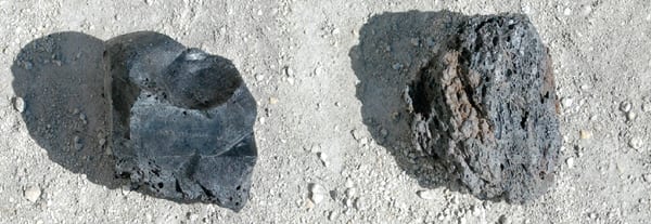
The dry method of cleaning typically involves a combination of vacuuming and air lancing to remove the ash from the reactor; in gas applications, it also may include removal of insulation debris and/or rust scale. This process is typically very effective where the modules have flyash buildup but no LPA in the catalyst. This can be performed in situ or off-site, depending on site logistics and outage considerations (Figure 6).
6. Dry cleaner. Dry cleaning using vacuuming/air lancing can reduce catalyst fouling due to buildup of large-particle ash and ash fines. The example below shows reduction from 30% to 50% on average.
Courtesy: Cormetech Inc.
Wet cleaning of severe ash buildup on a catalyst cleaning is referred to as washing, regeneration, or rejuvenation (Figure 7), depending upon the process and aqueous solution used. This is a more elaborate cleaning process that removes most of the chemical buildup on the catalyst surface. The process generally restores the catalyst activity lost to both gross and fine physical blockage. In addition, the process can be used to restore all or a portion of the catalytic activity lost due to chemical poisons.
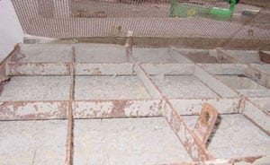
a. Removal of ash

b. Vacuuming
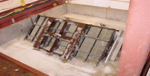
c. Washing using a cleansing solution

d. Bubbling and aeration under pressure
7. Rejuvenation. These images depict some of the stages in SCR cleaning using the rejuvenation process.
Generally, the regeneration process consists of the following steps:
1 Baseline testing of the catalyst to assess performance recovery.
2 Blowing and vacuuming ash off the catalyst.
3 Adding ultrasonic energy, bubbling air in the solution and/or physically moving the module to remove any remaining ash.
4 Washing the catalyst module using a cleansing solution. This may need to be done multiple times, with different solutions, in accordance with the system vendor’s recommendations.
5 Drying each catalyst module using forced hot air.
6 Testing the catalyst elements to verify that the cleaning has met the established goals.
Regeneration/cleaning must be considered at every plant where the condition of the catalyst condition and its remaining service life dictate it. If it is determined to be economically advantageous to the plant, catalyst cleaning can extend the active life span of a catalyst and be an essential part of a catalyst management program for a plant. In all cases, the process should be prequalified on samples prior to implementation of the full-scale process. Items for consideration include the level of activity recovery (physical or chemical), the impacts on SO2 conversion and mercury oxidation, cost, schedule, and any applicable warranty conditions.